😱
Thanks for clearing that up.
Seems like this might be the best bet, then:
10ft Premier Series XLR Male to RCA Male 16AWG Cable (Gold Plated) - Monoprice.com
Seems like this might be the best bet, then:
10ft Premier Series XLR Male to RCA Male 16AWG Cable (Gold Plated) - Monoprice.com
That'll be perfect. You'll be able to get a bit better performance with an actual differential connection, but the cable linked to above will get you most of the way there.
~Tom
The THAT Situation
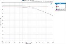
So... I figured I'd quantify exactly how much common-mode rejection ratio (CMRR) is lost by using pseudo-differential connections and by using a pure single-ended connection. See attached.
The single ended (SE) configuration corresponds to bypassing the THAT1200 entirely. That's the blue line at 0 dB (no CMRR). This is exactly the same as any other single-ended amp.
Pseudo-differential (Pseudo-DIFF) shows a dramatic improvement in CMRR. The CMRR plot assumes a 10 Ω imbalance between the (+) and (-) pins. The CMRR below 1 kHz is comparable to that of the true differential (DIFF) connection. Above 1 kHz, the CMRR rolls off quickly when using a pseudo-differential connection
It appears as if the CMRR is actually better when the (+) input, Pin 2, has higher drive impedance than the (-) input. That I believe is an artifact of the measurement. I'll need to analyze this in greater detail, but I bet the gain changes slightly when the 10 Ω imbalance is introduced. This results in a slightly lower common-mode component on the output of the THAT, which in turn is measured as a lower voltage on the MOD86 output, hence, is interpreted as a higher CMRR. The opposite is true when the imbalance is on the (-) input, Pin 3.
The true differential (DIFF) connection shows the best performance with nearly 90 dB of CMRR across frequency, rolling off to 87 dB at 20 kHz. This is truly stellar CMRR performance an is the main reason I included the THAT1200 in the design.
~Tom
Attachments
Last edited:
I assume this is a demonstration of external noise rejection. If there is no noise, is there any relationship with signal transmission?
The plot shows the common-mode rejection. It shows how much the common-mode noise will be attenuated by the Modulus-86 amplifier. If the input wires are tightly coupled (twisted pair microphone cable, for example) the noise injected on the cable will be (mostly) common-mode, hence, rejected by nearly 90 dB by the Modulus-86 when using the differential input. Even when using a pseudo-differential connection, there is significant noise rejection.
For any amplifier with a single-ended input there is no rejection at all. That's represented by the blue line at 0 dB in the plot.
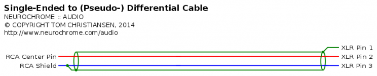
Attached figure shows the connections for a pseudo-differential cable that can be used to connect the Modulus-86 to a single-ended source. You can find a link to a commercially available cable a few posts back.
~Tom
For any amplifier with a single-ended input there is no rejection at all. That's represented by the blue line at 0 dB in the plot.
Attached figure shows the connections for a pseudo-differential cable that can be used to connect the Modulus-86 to a single-ended source. You can find a link to a commercially available cable a few posts back.
~Tom
Attachments
Incredible. Thanks for taking the time, Tom. I'm not quite ready to buy boards yet, so I hope you'll have good supply well into the new year.
My experience is that interconnects causes impedance variation over the audio band above 1 KHz, using a balanced connection balances the impedance between the two lines minimizing the effects of varying impedance. I have not evaluated the pseudo-differential cable though. Seems to be an interesting experiment.
The issue I see with balanced output is that you need to have both lines having the same source impedance curve, otherwise we are actually amplifying the difference.
Would be interested in seeing the input impedance curves of +~-, +~GND, -~GND with minimum length cabling.
The issue I see with balanced output is that you need to have both lines having the same source impedance curve, otherwise we are actually amplifying the difference.
Would be interested in seeing the input impedance curves of +~-, +~GND, -~GND with minimum length cabling.
Last edited:
Incredible. Thanks for taking the time, Tom. I'm not quite ready to buy boards yet, so I hope you'll have good supply well into the new year.
You must have read my mind... I will have an optimized (linear) supply board available in early January. The board will feature a diode bridge with on-board heat sink, snubbers for the diodes, bleeder resistors, and two snap-in capacitors (10 mm pin spacing, up to 40 mm diameter). The supply board is intended to supply two Modulus-86 boards.
~Tom
The issue I see with balanced output is that you need to have both lines having the same source impedance curve...
True. Thankfully, that's relatively easy to obtain with a differential driver. There are ways to screw that up, however. That seems to be the mantra of precision circuit design... 🙂
~Tom
You must have read my mind... I will have an optimized (linear) supply board available in early January. The board will feature a diode bridge with on-board heat sink, snubbers for the diodes, bleeder resistors, and two snap-in capacitors (10 mm pin spacing, up to 40 mm diameter). The supply board is intended to supply two Modulus-86 boards.
~Tom
I actually meant "a good supply of Modulus-86 boards" not "a good supply board" but either way that supply board sounds cool. 😀
I actually meant "a good supply of Modulus-86 boards" not "a good supply board" but either way that supply board sounds cool. 😀
Funny... Different context, different connotation. My brain was off in Power Supply Land when I read your post. 🙂 No worries on the supply of boards. While they do move at a comfortable pace, more can be made, and I have no plans of going away anytime soon.
~Tom
I have studied the snubbering of rectifying diodes, do they really cause a measure or audible difference in the amplifier performance?You must have read my mind... I will have an optimized (linear) supply board available in early January. The board will feature a diode bridge with on-board heat sink, snubbers for the diodes, bleeder resistors, and two snap-in capacitors (10 mm pin spacing, up to 40 mm diameter). The supply board is intended to supply two Modulus-86 boards.
~Tom
Last edited:
I have studied the snubbering of rectifying diodes, do they really cause a measure or audible difference in the amplifier performance?
In theory, when the rectifying diodes turn off, they will excite the parasitic inductance and capacitance in the transformer secondary, producing ringing. The most effective way to deal with this ringing is to apply an RC snubber across each diode, however, this requires that the snubber is optimized for the specific transformer and layout used. This, generally, is beyond the scope of the typical DIY project. If you get the snubber components wrong, you can actually make matters worse.
A more general approach is to use a capacitor (100 nF or so) across each secondary winding. This may not be the optimum snubber, but it will always make the circuit perform better, never worse. This is my approach.
That said, with the GBU2510 rectifier bridge I'm messing with, I actually don't see any oscillation when the rectifier turns off. I'm wondering if the bridge rectifier has the snubber built in. It is also possible (probably more likely) that the rectifier diodes are fast turn-off, soft recovery types. If the diodes turn of quickly but do so with a smooth recovery profile, the parasitic RC wouldn't get excited as violently and ring less, if at all. Regardless, no oscillation - no problem...
~Tom
Last edited:
Very nice. Expensive, though... $9. They won't provide any benefit over the $3 GBU2510 I'm using, however. At least not in my application.
The supply board was submitted to the fab about an hour ago. It should be available before the end of the year.
~Tom
The supply board was submitted to the fab about an hour ago. It should be available before the end of the year.
~Tom
Tom, I've posted your thread and added a link to your site on my forum and a member bought your PCBs and will try them. I will most likely do as well later on, once I'm done with my current project load.
Ciao!
Do
Ciao!
Do
A more general approach is to use a capacitor (100 nF or so) across each secondary winding. This may not be the optimum snubber, but it will always make the circuit perform better, never worse. This is my approach.
Fast/soft recovery is nice.
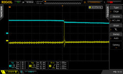
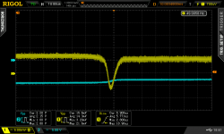
What I do is put across the secondary, a small cap like 4.7nF, and a 100nF in series with a 1k pot. I connect the scope to the secondary through a highpass (like 100pF/10k) which removes the mains frequency, turn the pot until the ringing is damped, and replace it with a fixed resistor. Works very well and simple to do...
Scope shots (in that order) are : no snubber, pot too low, pot too high, just right.
Attachments


If snubbers are your thing, I highly recommend a read through this for a practical, no b/s solution:
http://www.diyaudio.com/forums/powe...sformer-snubber-using-quasimodo-test-jig.html
http://www.diyaudio.com/forums/powe...sformer-snubber-using-quasimodo-test-jig.html
I found the opposite..................A more general approach is to use a capacitor (100 nF or so) across each secondary winding. This may not be the optimum snubber, but it will always make the circuit perform better, never worse. ..............
I was working (via Email) with the amplifier designer.
I had included the rectifier capacitor size, type and manufacturer as specified.
I kept getting instability in the amplifier and everything he suggested did not work to cure it.
I looked in frustration at the sole capacitor "ringing frequency changer" and removed it.
The instability was gone. The ringing of the transformer/rectifier was putting an interference signal into the amplifier and causing it to operate on the edge of instability.
That was about 6years ago.
I then searched back through the Forum and found many posts by EVA. He/she showed why a cap across a PSU or across a big electro or across a rectifier is COMPLETELY wrong!
I have NEVER used a sole capacitor as a snubber since.
A snubber must have a damping resistor !!!!!!!!!!!!!!
Peufeu states it well.turn the pot until the ringing is damped, and replace it with a fixed resistor. Works very well and simple to do...
Scope shots (in that order) are : no snubber, pot too low, pot too high, just right.
Last edited:
- Home
- Vendor's Bazaar
- Modulus-86: Composite amplifier achieving <0.0004 % THD+N.