A small heatsink will keep the lm3886 happy without fans. Something like 5"*3"*1.5" will work for cooling.
Define "keep happy". How much power are you able to get out of your LM3886 in that configuration before the SPiKe protection kicks in? Have you measured this?
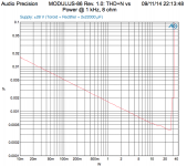
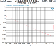
Attached to this post are two plots. Notice how the max output power in one plot is about 28 W, whereas the other goes to about 35 W.
In the first plot, I used a SilPad between the LM3886TF (isolated package) and the heat sink. I didn't want to deal with the mess of thermal grease and figured the SilPad should be good enough. The result is that the amp only provides about 28 W before the LM3886 overheats and the SPiKe kicks in.
In the second plot, I applied a thin coat of thermal grease between the LM3886TF and the heat sink. With the better thermal contact, I'm now able to drive the amp to clipping without overheating the IC.
I will encourage those who would like to understand the thermal design to take a look at my Taming the LM3886 - Thermal Design page.
~Tom
Attachments
Last edited:
I've never gone into spike protection with this amp. keeping my amp happy means no spike, warm sinks and slightly warmer chip. I dont measure the power output.
I did read your linked page and its incredibly well written and informative. I hope you intend to keep your site up for many years.
Understanding thermal design and being able to follow directions are two different things. Understanding and following are not absolutes and each happens to a degree for us all. I've read quite a bit on heatsink sizing for several different amps but especially this chip. Of course all the Nat Semi app notes regarding lm3886. Your web page though has been the most enlightening. Maybe for how its written maybe because what I've read allowed me to understand more at this point in time better than previous docs. Either way it was good to read how you explained sizing for an all out sine wave attack on the amp vs sizing for real listening.
Aavid Thermalloy used to have a heatsink simulator that I've found helpful and also enlightening to see how heat spread changes with chip position or sink dimension changes.
I know the sink I suggested will do a good job keeping lm3886 "happy" in most conditions. Maybe Bill has more extreme conditions. I'm sure following your cookbook would be helpful for him.
Last edited:
I've never gone into spike protection with this amp. keeping my amp happy means no spike, warm sinks and slightly warmer chip. I dont measure the power output.
Ok. So for "normal listening volumes" (whatever that may be for you) at whatever supply you're using, the heat sinks get "warm" and the ICs "slightly warmer". There's not a lot of quantifiable data there...
When taking the plots I posted in Post #281, I measured the case temperature of the LM3886 while the AP performed the power sweep. The case temperature hit over 125 ºC near the end of the sweep. This while mounted on a 0.4 ºK/W heat sink (about 1 kg of aluminum, 10 mm thick with 25 mm fins 150 mm tall).
I'm thinking you may be the Joe Schmo on the Internet, I mention in Thermal Design Example #4: Other Solutions. No offense intended, you just seems to fit the profile... 🙂
Your point is valid, however: At idle the chip dissipates a few watt. You don't need much heat sink to dissipate that. If the chip hardly ever delivers more than a few watt to the speaker (and in most cases, it doesn't) there's no need for a large heat sink. This only works as long as the chip doesn't deliver much power to the load. Should someone decide to crank the volume knob and allow the chip to deliver, say, 10 W, I guarantee you that you'll hit the thermal limit within a few minutes.
If you don't want to fit a sizable heat sink to the LM3886, at least fit a thermal switch so someone doesn't burn their fingers on the heat sink, if exposed to the user.
The bottom line is that there's no cheating physics. If power is dissipated, heat results. There's no way around that.
If you have a dummy load (8 Ω resistor of significant power handling capability), a function generator (or sound card + software), an oscilloscope, and a multimeter with RMS readout, you can easily measure the max output power. Apply the load resistance to the amp. Connect the multimeter and oscilloscope on the output of the amp. Connect the function generator to the input of the amp. Run a 100 Hz sine wave into the amp and turn up the amplitude until the amp either clips or the SPiKe protection engages (either is easy to identify on the scope). Measure the RMS AC voltage on the output of the amp. Calculate the output power.
I suggest using 100 Hz for the test frequency rather than the more common 1 kHz as cheaper meters tend to cut off above 400 Hz.
I did read your linked page and its incredibly well written and informative. I hope you intend to keep your site up for many years.
Thank you. I'm glad you enjoyed it. I appreciate your feedback.
I plan to keep adding to the site and keep it running for years to come. No worries. I'm not going away anytime soon. As long as I'm having fun and people appreciate my work, life's good.
~Tom
In the spirit of Tom's "revealing all", 😀, the heatsinks I used "for normal listening" were rated 0.9ºC/W, and were orientated for optimal convection cooling. Only under the most extreme, continuous sine wave like music playback - this being an operatic soprano hitting a big note and holding it for a decent period, system at maximum volume - did the units momentarily activate their protection ...
Last edited:
I have been mulling over the thermal question to. I'm very tempted to build these, but one of my pairs of speakers is a solid 6Ohms, the other 4 and neither are very efficient (84dB/W area). Room is small, I don't headbang so should be fine, but would be nice to give the chips the best chance.
Use ±24 to ±28 V rails. Use ±20 V rails if you want to minimize the heat sink size. The max output power scales with voltage squared, so you'll find that at ±20 V you'll get quite a bit less peak output power than at ±28 V. In return, you get less power dissipated in the amplifier and can live with a smaller heat sink. That's my recommendation.
If you need to drive 4 Ω loads at power levels beyond 30-35 W, I recommend using two Modulus-86 boards in parallel. 30-35 W would give you about 100 dB SPL at 1 m with 84 dB/W*m efficient speakers. That's pretty darn loud.
An internal heatsink with forced cooling does give the heat removal, but finding a quiet enough fan so as to not add to the room noise floor becomes a challenge.
I'm not a fan of fans for the reasons you mention. If you don't like The Engineering Solution, I suggest reading through The Crest Factor, The Duty Cycle, and Other Solutions. You'll probably find that a small external heat sink fitted with a thermal cutoff switch will suit your needs.
My recommendation is a good one and I'm sure you can run full blast on that size sink but I'm not asking you to take my word without checking.
I think that's a reckless recommendation. You cannot run full blast on a heat sink that small, assuming "full blast" means peak power dissipation on ±25 V rails with a 4 Ω load and sine wave excitation. I go through the math on my website.
If "full blast" means 90 dB SPL at 1 m using 84 dB/W*m efficient speakers, then your right. But that's only a few watt delivered to the speaker. That's hardly full blast for a 68 W rated amp (data sheet figure, 4 Ω, ±28 V rails).
Heat sinks of the physical size udailey's suggesting around 1.7 C/W; OK if one's looking for a few volts peak on ±28 V, high by a factor of at least two if the goal's maximum swing.
Exactly. If "full blast" means 90 dB SPL at 1 m using 84 dB/W*m speakers, that's true. 90 dB SPL is plenty loud for me.
However, if "full blast" means peak power dissipation on ±25 V rails with a 4 Ω load, 34 W will be dissipated in the LM3886. The output power in this case is about 30 W. The temperature of the heat sink will be 25+1.7*34 = 83 ºC, assuming the heat sink is external and that the room temperature is 25 ºC. The die temperature will be 2*34+83 = 151 ºC - the SPiKe system will engage. 83 ºC is not safe for an external heat sink... It will result in instant burns if touched. You can move the heat sink inside the chassis, but without forced air cooling, the temperature inside the chassis will be considerably higher than the external air temperature, even with good ventilation. This results in an even higher die temperature.
Above math assumes 2 ºK/W thermal resistance from the heat sink to the die, which, based on my experiments with the isolated LM3886TF, is very optimistic to say the least.
When physics collides with expectations desire loses. 😉
Physics always win.
~Tom
Last edited:
Check this doc :
https://www.onsemi.com/pub/Collateral/AN1040-D.PDF
For my next project, I really don't want to mess with screwing devices in heatsinks, so I'm thinking about using spring clips.
The force is much more uniform, it is applied where it is needed (ie, at the center of the package above the silicon die, not just on the tab)... lots of advantages.
Also silpads are a bit "springy", so when using a screw on the tab, the tab will compress the silpad correctly, but the rest of the device won't, it will basically do like the first figure in the pdf above... with force applied on the center of the chip, it doesn't.
Aluminium oxide is an excellent insulator... Something I want to try is simply mounting the device on the (anodized) heatsink, with a bit of thermal paste and nothing else. The anodized surface must not have any scratches, so the device should be held by a spring clip, not a screw...
The numbers are already in the datasheet.you say plug and chug, yet seem happier to write lots of words than throw down a few numbers. Most curious. And I will have fun. That would be the only reason for going this route. Isn't that the point of this hobby.
The calculation method is in the app note and the datasheet.
guessing is not required.
"Full blast" means at least two quite different things and depends totally on the operating conditions.
Sinewave testing to maximum unclipped power is one operating condition.
This appears to be what the two graphs are showing when the distortion suddenly skyrockets @ ~28W or ~35W, post281
That is clearly "full blast" and shows that the chipamp is limited by the Rth c-s of the case to sink interface.
A different operating condition is using the chipamp style amplifier to play music files.
Here the average power output is much below the peak power output.
Typically peak:average ratio is from 10db to 30dB.
i.e for a 68W (32.98Vpk, 23.32Vac) chipamp the average output power is between 6.8W (10.4Vpk, -10dB ref peak) and 68mW (1.04Vpk, -30dB ref peak).
"full blast" here means just reaching clipping on the highest peaks, but not exceeding clipping.
The average temperature of the heatsink when reproducing music with a peak:average ratio of around 20dB will be little more than the quiescent temperature.
Peak transients that naturally re-occur regularly during the music passage will raise the chip temperature and raise the case temperature and raise the sink temperature. But these events are short lived. The temperatures don't rise to anywhere near the previous full power testing condition. The momentary peaks subside and junctions temperatures start to return to the average levels.
Spike and other limiting does not get activated due to temperature.
It's current limiting that generally gets activated during music reproduction if adequate cooling has been provided.
The two previous paragraphs describe conditions that can both be "full blast".
However Spike is linked to temperature. It's limiting does take account of chip temperature.
A chip that is operating at a hotter temperature will limit earlier than a chip that is cooler. There is little data from National on this.
The effect of this variable limiting is that a cool chip will activate the limiters less often than a warm chip and very much less often than a hot chip.
Big sinks with their attendant cooler operation will sound nicer than small sinks.
Last edited:
The numbers are already in the datasheet.
The calculation method is in the app note and the datasheet.
guessing is not required.
Yes they are and I have read them, for the 3rd time was just musing on mechanical solutions where you don't want an isolated heatsink. Is it a sin to be interested in different packaging solutions? Or wrong of me to have a desired operating point then design the thermal solution so I know that is guaranteed?
If you need to drive 4 Ω loads at power levels beyond 30-35 W, I recommend using two Modulus-86 boards in parallel. 30-35 W would give you about 100 dB SPL at 1 m with 84 dB/W*m efficient speakers. That's pretty darn loud.
<snip>
I'm not a fan of fans for the reasons you mention. If you don't like The Engineering Solution, I suggest reading through The Crest Factor, The Duty Cycle, and Other Solutions. You'll probably find that a small external heat sink fitted with a thermal cutoff switch will suit your needs.
~Tom
Hi Tom,
Sorry again for the noise I seem to have dragged onto the thread. I'm looking for a solid 50W into 4Ohms and was considering paralleling or bridging until I studied the data sheets and decided that it should be possible with careful optimisation of the thermal design. Back in the dark recesses of my brain I used to do thermal work on satellite payloads, just shame I cant get access to all the fancy stuff we used back then anymore.
But I'll do this offline. For some reason I have been tagged as an idiot without any formal education who cannot read a data sheet by some posters and I really don't want to start arguments where there are none needed.
amp designers are expected to design.
amp builders are mostly unable to design.
You choose which parts you can design and which parts you copy, because you can't design.
That is what I do.
amp builders are mostly unable to design.
You choose which parts you can design and which parts you copy, because you can't design.
That is what I do.
amp designers are expected to design.
amp builders are mostly unable to design.
You choose which parts you can design and which parts you copy, because you can't design.
That is what I do.
Your point being?
you asked a question.Is it a sin to be interested in different packaging solutions?
I replied with what I do.
What I fail to see is in what sense this is different from an LM3886 preceeded by a buffer. The buffer can in and by itself not lower the distortion of the LM3886, nore improve its PSSR. So, what is the fuzz about?
Yes, but in what way is two chips following each other composite, other than the first one being a buffer to the second?
The second amp is in the feedback loop of the first, so LM3886 handles power, while the small opamp handles precision and corrects the power amp's distortion.
Any particular design reason for the 797 or do you just like it? There's some discussion of control device selection back on page 19 of this thread but that was looking at lower bandwidth parts than the 49710.Just thought that it would be great to have a power AD797 amp. 🙂
The second amp is in the feedback loop of the first, so LM3886 handles power, while the small opamp handles precision and corrects the power amp's distortion.
You are right, I was looking at the wrong schematic.
I link to that on my website, actually. It is indeed a good reference.
For my next project, I really don't want to mess with screwing devices in heatsinks, so I'm thinking about using spring clips.
If you can find a clip that fits, that would be an elegant solution. If not, a piece of U channel strapped across the ICs would work as well.
~Tom
- Home
- Vendor's Bazaar
- Modulus-86: Composite amplifier achieving <0.0004 % THD+N.