Can we bridged with previous version?
I would not recommend that. What you can do is to bridge two MOD86 Rev. 1.0 for one channel and bridge two MOD86 Rev. 2.0 for the other channel.
Now all we need is some comparisons Tom maybe you could start another thread on real evaluations between apples to apples amps..etc...
Well... I've posted data for both the MOD86 Rev. 1 and MOD86 Rev. 2. I'm not sure how I can get that any more real or apples-to-apples.
~Tom
Tom,
If you can, do an overlay of the version 1.0 and 2.0 measurements. It's easier to see differences. You can just use different colors.
Then with future comparisons we can do the same with version 2.0 versus NCore 400, etc...
Just give me a few more days and I'll ship my NCore to you, no problem.
Best,
Anand.
I am planning to get set up a bit better for amp comparison. It's behind the Parallel-86 project, though. The PAR86 should come together pretty quickly, though (famous last words).
I'll be happy to show measurements of both the MOD86 R1.0 and MOD86R2.0 done on the same setup. No worries.
~Tom
I'll be happy to show measurements of both the MOD86 R1.0 and MOD86R2.0 done on the same setup. No worries.
~Tom
MOD86 R2.0 + SMPS300RE
A while back, I promised to take measurements on the Modulus-86 when powered by a Connex Electronic SMPS300RE. Attached graphs are from the Modulus-86 Rev. 2.0 when powered by the SMPS300RE.
I bought the ±30 V version directly from Connex. The shipping ran about $20 and the supply was delivered within 2-3 weeks as I recall. Not too shabby.
~Tom
Attachments
-
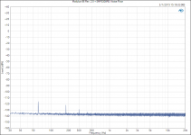
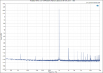 Modulus-86 Rev. 2.0 + SMPS300RE_ Harmonic Spectrum @ 1 kHz, 38 W, 8 ohm.png41 KB · Views: 803
 -
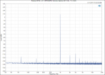 Modulus-86 Rev. 2.0 + SMPS300RE_ Harmonic Spectrum @ 1 kHz, 1 W, 8 ohm.png39.2 KB · Views: 810
 -
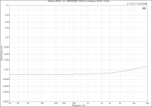 Modulus-86 Rev. 2.0 + SMPS300RE_ THD+N vs Frequency @ 38 W, 8 ohm.png37.2 KB · Views: 804
 -
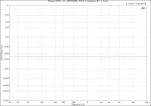 Modulus-86 Rev. 2.0 + SMPS300RE_ THD+N vs Frequency @ 1 W, 8 ohm.png36.2 KB · Views: 795
 -
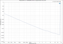 Modulus-86 Rev. 2.0 + SMPS300RE_ THD+N vs Output Power @ 1 kHz, 8 ohm.png42.6 KB · Views: 795
 -
 Modulus-86 Rev. 2.0 + SMPS300RE_ Noise Floor.png34.7 KB · Views: 235
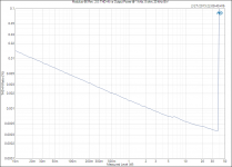
While measuring the MOD86 with the SMPS300RE, I found a way to clean up the measurement setup and eek out the last bit of performance from the APx525. Here are the measurements for the Modulus-86 Rev. 2.0 with an unregulated supply (toroid + bridge rectifier + 2x22000 uF). The THD vs Output Power is the same as I posted earlier. I'm just adding it here for completeness.
~Tom
~Tom
Attachments
-
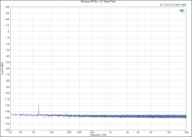 Modulus-86 Rev. 2.0_ Noise Floor.png34.5 KB · Views: 182
 -
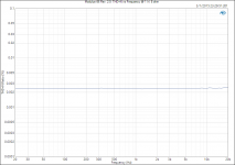 Modulus-86 Rev. 2.0_ THD+N vs Frequency @ 1 W, 8 ohm.png35.8 KB · Views: 176
 -
 Modulus-86 Rev. 2.0_ THD+N vs Frequency @ 38 W, 8 ohm.png36.7 KB · Views: 193
 -
 Modulus-86 Rev. 2.0_ Harmonic Spectrum @ 1 kHz, 1 W, 8 ohm.png38.6 KB · Views: 223
 -
 Modulus-86 Rev. 2.0_ Harmonic Spectrum @ 1 kHz, 38 W, 8 ohm.png40.7 KB · Views: 257
 -
 Modulus-86 Rev. 2.0_ THD+N vs Output Power @ 1 kHz, 8 ohm, 20 kHz BW.png38.5 KB · Views: 177
as always, very good figures showing a job well done.
I have a question:
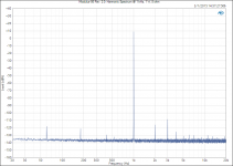
The 60Hz and harmonics is still showing with the SMPS as the PSU.
Why?
Is the mains interference getting in via a route that is not from the PSU?
Is it an attribute of the "test" cabling/setup?
I think it was Sy a couple of years ago that found a massive reduction in measured mains interference when changing from single ended testing to balanced connections for all the test gear cables.
I have a question:
The 60Hz and harmonics is still showing with the SMPS as the PSU.
Why?
Is the mains interference getting in via a route that is not from the PSU?
Is it an attribute of the "test" cabling/setup?
I think it was Sy a couple of years ago that found a massive reduction in measured mains interference when changing from single ended testing to balanced connections for all the test gear cables.
as always, very good figures showing a job well done.
Thank you.
I have a question:
The 60Hz and harmonics is still showing with the SMPS as the PSU.
Why?
There is actually a bit of 60 Hz ripple present on the output of the SMPS300RE, in addition to the 90-120 kHz ripple from the switching. The SMPS300RE switches directly off the rectified mains voltage, which may be the reason for this.
Is the mains interference getting in via a route that is not from the PSU?
Is it an attribute of the "test" cabling/setup?
I think it was Sy a couple of years ago that found a massive reduction in measured mains interference when changing from single ended testing to balanced connections for all the test gear cables.
Well, yeah... If you have a ground loop that is part of the signal path in your test setup, you will see a dramatic increase in mains-related interference. That's life in precision analog.
The improvement in my test setup came from better grounding to ensure that the AP wasn't floating, and from using the precision ADC rather than the high-bandwidth ADC for the measurements with 20 kHz bandwidth (so the FFT plots and THD vs Power @ 1 kHz).
I suspect the last little bit of 60 Hz hum in my setup is from inductive coupling to the environment. My test setup is the Modulus-86 Rev. 2.0 board mounted on a heat sink sitting on my workbench. I bet the last remaining 60 Hz will disappear once the circuit is in a grounded enclosure. That said, the last little bit of mains hum comes in at -120 dBV, 15 dB above the noise floor of the amp. -120 dBV is 1 µV. Pretty small... 🙂
How important is the PCB or is using the best PCB important?
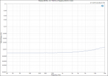
The circuit board layout is just as big a part of the circuit as the components on the board. Without a good circuit board there is no way I would have been able to achieve the stellar performance of the Modulus-86. If you compare the THD vs frequency at 1 W into 8 Ω for Modulus-86 Rev. 1.0 and Rev. 2.0, you will notice that 1.0 has a slight rise starting at about 5-6 kHz, whereas Rev. 2.0 is flat from 20 Hz to 20 kHz. That improvement is the result of a very slight change in the grounding of one resistor in the circuit. The change is so minor that you wouldn't notice it when comparing the boards side-by-side, unless I pointed it out.
This minute change of the layout is also responsible for the 10+ dB reduction in residual mains hum.
It's amazing what the removal of about 2 mm of copper traces will do for you.
Where and how to order? I dont find the info. The thread is too long.
My signature should provide some clues... 🙂 Here's the deep link to the page on my website where you go to order: Modulus-86 Rev. 2.0: Composite amplifier achieving 0.00014 % THD.
I have four boards left in stock. When making significant changes, I order a small batch of boards first. I only received 16 boards in the first batch. I have another 100 boards in the fab. They should arrive in about two weeks.
~Tom
Last edited:
Hi Tom,
have you taken measurements (i.e. using version one) in a stereo or multi-channel configuration (sharing a common PSU)?
I would be interested in your recommended integration strategy, particularly in how you would advise to extend the benefits of your grounding scheme into a system as a whole (i.e. a stereo amp, an active speaker, etc.).
Thanks,
Sebastian.
have you taken measurements (i.e. using version one) in a stereo or multi-channel configuration (sharing a common PSU)?
Not yet but I am planning to build a two-channel amp for myself and will measure all the parameters with both channels driven. I'll also measure crosstalk and such.
I also have a customer-friend request for a completed amp, so there will be plenty of opportunities to measure a stereo amp. The Parallel-86 is higher priority, though.
I would be interested in your recommended integration strategy, particularly in how you would advise to extend the benefits of your grounding scheme into a system as a whole (i.e. a stereo amp, an active speaker, etc.).
That is in part why I developed the Power-86 board. The most important aspect of the grounding topology is the hand-off between the power ground, which handles the return current from the load impedance, and the reference ground, i.e. the ground plane for the controlling op-amp, DC servo, and differential input amp. I performed several simulations and lab experiments to develop the optimal configuration. The difference in THD above 5 kHz can easily be over 10x between the optimal layout and a layout where the reference ground joins the power ground at a non-optimal point.
Thankfully, all this is handled on the Modulus-86 board so as long as the builder connects the board as shown in the design documentation, they will get stellar performance.
~Tom
Last edited:
there will be plenty of opportunities to measure a stereo amp. The Parallel-86 is higher priority, though.
Of course, good to know you've got this on your list.
all this is handled on the Modulus-86 board so as long as the builder connects the board as shown in the design documentation
Famous last words from a developer before exposure to real world users... 😉
Thanks Tom,
Sebastian.
Famous last words from a developer before exposure to real world users... 😉
Thanks Tom,
Sebastian.
I know what I'm doing, but having built one referencing the build docs I can safely say anyone who gets this wrong shouldn't have been allowed to plug in their soldering iron in the first place. For some this is not what they want from DIY, but for many it is a very attractive proposition.
Can i connect unbuffred source to M-86 bufferd input?
Yes you can. Your source will need to handle the volume control as the MOD86 does not include volume control.
~Tom
When you hook two channels to the same power supply, there is still a cross talk concern.Not yet but I am planning to build a two-channel amp for myself and will measure all the parameters with both channels driven. I'll also measure crosstalk and such.
I also have a customer-friend request for a completed amp, so there will be plenty of opportunities to measure a stereo amp. The Parallel-86 is higher priority, though.
That is in part why I developed the Power-86 board. The most important aspect of the grounding topology is the hand-off between the power ground, which handles the return current from the load impedance, and the reference ground, i.e. the ground plane for the controlling op-amp, DC servo, and differential input amp. I performed several simulations and lab experiments to develop the optimal configuration. The difference in THD above 5 kHz can easily be over 10x between the optimal layout and a layout where the reference ground joins the power ground at a non-optimal point.
Thankfully, all this is handled on the Modulus-86 board so as long as the builder connects the board as shown in the design documentation, they will get stellar performance.
~Tom
When you hook two channels to the same power supply, there is still a cross talk concern.
Sure. How much you should be concerned depends on how much signal-dependent ripple voltage develops across the power supply and the power supply rejection ratio of the "victim" channel. Given the incredibly large PSRR of the Modulus-86, I would expect the crosstalk to be barely measurable.
~Tom
The critical issue is handling of the ground between the channels. I think you will find this out when you start comparing mono mono vs stereo with mono supply.
a mono block that is connected to Mains Safety Earth is quite different from a stereo that is connected to Mains Safety Earth.
The way the Stereo is connected to Mains safety Earth makes a big difference to the final performance of the amplifiers.
As far as I know, this potential degradation in amplifier performance has nothing to do with the amp's PSSR, nor with crosstalk.
It has all to do with inadvertent loop areas.
The way the Stereo is connected to Mains safety Earth makes a big difference to the final performance of the amplifiers.
As far as I know, this potential degradation in amplifier performance has nothing to do with the amp's PSSR, nor with crosstalk.
It has all to do with inadvertent loop areas.
Well, the ground loop in stereo amp connection is another issue, but how do you rule out cross talk and PSRR issues. I see no basis of ruling those out, perhaps you can elaborate? As a matter of facto, two equipment connect to each other and each independently connected to protection earth creates a loop as well. The issue is how the current is going to flow.
Last edited:
- Home
- Vendor's Bazaar
- Modulus-86: Composite amplifier achieving <0.0004 % THD+N.