So doesn't the servo op-amp suffer from drift/flux etc?
(Must admit I remove the flux, and never noticed much drift even with discrete ciruits even over many years, but hey ho).
The servo op-amp has no DC gain.
The servo amps are also very high DC precision and have little to no drift relative to the needs of this circuit.
The servo amps are also very high DC precision and have little to no drift relative to the needs of this circuit.
I was talking about the opamp that is used to do the servo'ing. It sounds like you are referring to the entire amplifier. The opamp for the servo function doesn't need to be high precision. That's the beauty - you can use a slow low bandwidth opamp, a 741. The time constant can be seconds, should be much much slower than the main feedback loop.
Last edited:
The worst case input offset of the LME49710 is 0.7 mV worst case. That would lead to about 7 mV of DC offset on the amp output. That's kinda-sorta not bad but not stellar either. Then you add the impact of the 72 nA of input bias current (worst case). Even if you were to compensate for the input bias current, you still have 65 nA (worst case) of input offset current to deal with. It all adds up.
For a state of the art amp, I expect 1 mV or less for the DC offset. Also as others have pointed out, if the source has a DC offset, that'll be amplified by the amp. That's not a good scenario.
Regarding servo amps, you do want an amp with low input bias current for the DC servo amp as the impedances in the filter network in the servo tend to be high. This usually limits you to CMOS input opamps. You also want to choose a filter topology that ensures good stop band attenuation even as the loop gain of the servo amp rolls off or the DC servo will degrade the THD within the audio range. So you're looking at something other than a Salen-Key filter. The design of DC servos is an often neglected topic in amplifier design books. That's a bit of a shame.
Tom
Last edited:
The servo op-amp has no DC gain.
It needs dc gain to work properly! Ideally it should have no gain at audio frequencies.
The worst case input offset of the LME49710 is 0.7 mV worst case. That would lead to about 7 mV of DC offset on the amp output. That's kinda-sorta not bad but not stellar either. Then you add the impact of the 72 nA of input bias current (worst case). Even if you were to compensate for the input bias current, you still have 65 nA (worst case) of input offset current to deal with. It all adds up.
For a state of the art amp, I expect 1 mV or less for the DC offset. Also as others have pointed out, if the source has a DC offset, that'll be amplified by the amp. That's not a good scenario.
Regarding servo amps, you do want an amp with low input bias current for the DC servo amp as the impedances in the filter network in the servo tend to be high. This usually limits you to CMOS input opamps. You also want to choose a filter topology that ensures good stop band attenuation even as the loop gain of the servo amp rolls off or the DC servo will degrade the THD within the audio range. So you're looking at something other than a Salen-Key filter. The design of DC servos is an often neglected topic in amplifier design books. That's a bit of a shame.
Tom
Surely the +/-10mV o/p offset of the THATs1200 is the main issue. That could result in 100mV (assuming X10 gain) on the composite amp o/p. Up to about 50mV is generally considered acceptable.
In reality I suspect most Mod-86s would come in well below 50mV. Of course in a production environment the design choice has to be to include the servo. In the DIY world some people seem to enjoy copious SOTing e.g. Salas regs, Paradise phono etc. Must be that old protestant work ethic 🙂
this precisely how you should select a DC servo opamp................. The opamp for the servo function doesn't need to be high precision. ....................
Look for very low input offset voltage and very low drift of input offset with temperature. It's the combination of these two parameters that gives the precision in output offset of the amplifier.
It is preferable to look for very low input current.
Exactly, Andrew. I think gman is confusing bandwidth with precision. One wants good DC precision in the servo amps. One does not need super high bandwidth as it's not needed to support the servo's operation. That said, I've happily used OPA627s as servos and they work quite well. I've not done an exhaustive search, but I'd venture to guess that there are a larger number of precision op-amps suitable for servers than there are good audio op-amps.
I stand by what I said in Post #2284:
For the DC servo amp: Low input voltage offset. Low input bias current. Low input offset current. Low noise (yes, it can matter). The opamp can have lower bandwidth than the amps used for audio but will need to provide some loop gain throughout the entire audio range in order to get reasonable stop band attenuation of the DC servo (lowpass filter) throughout the audio range, so the GBP can't be too low.
I wouldn't go completely gaga over low drift. The modern precision opamps tend to be quite low drift to begin with. The other parameters are more important.
The OPA2277 used in the Modulus-86 was selected from these requirements. In the HP-1, I use the OPA2140 as I needed lower noise in the servo to avoid messing up the noise floor of the HP-1.
Jim Karki's app note on active filter design is worth reading if you're interested in designing high end DC servos. You can find a link to it at the bottom of my Modulus-86 page.
Tom
Last edited:
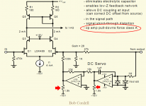
Bob Cordell's talk at Burning Amp 2016 included an interlude about DC servos. He said that he believed the opamp's output impedance was an important factor too. In fact he attaches quite beefy pulldown resistors to force the opamp output current to be waaaay bigger than zero at all times, namely, Class A. Since output transistor gm is proportional to current, and since output impedance is proportional to (1/gm), bigger current means lower output impedance.
I've attached a snip from one of Bob's presentation slides below. I'm the one who put the stupid looking red markings on the picture; Bob did not.
I've attached a snip from one of Bob's presentation slides below. I'm the one who put the stupid looking red markings on the picture; Bob did not.
Attachments
Hi,
Adding a passive filter after the servo is another nice touch. It will negate rising op amp output impedance with frequency and lower servo noise contribution.
Adding a passive filter after the servo is another nice touch. It will negate rising op amp output impedance with frequency and lower servo noise contribution.
I used to use 627 in servo on paradise builds, 277 does just as well at less than 1/10th the price.
[Cordell] said that he believed the opamp's output impedance was an important factor too.
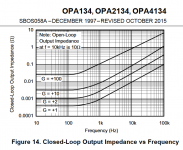
I'm curious what his justification was. The DC servo usually outputs into a feedback impedance on the order of 10s of kΩ. I wonder if what he's seeing is that the loop gain of the opamp goes up a bit as the output stage is biased hotter. High loop gain -> better stop band attenuation -> no impact of the DC servo on the overall amp within the audio range. The MFB filter I use makes better use of the opamp loop gain so I can get stellar performance without resorting to tricks such as dummy loads. Maybe the two approaches address the same underlying issue.
Interesting idea though.
Tom
Shoot him an email & ask.
I observe that the DC servo connects to the most sensitive node in the entire power amplifier, so you want it to be especially, particularly clean and error-free. If your goal is 22 bit resolution (signal-to-error ratio >= 133 dB), and if you also connect a 100 kilohm* resistor between servo-opamp and poweramp-inverting-input, then you want the servo opamp's output impedance to be less than 24 milliohms over the audio band. {Math: 100k/0.024 = (2 ** 21.99)}
But that's just me running my mouth; I don't speak for Bob Cordell, obviously.
*as is done in the attachment to post #2290 above
Attachments
It would be interesting to get some comments from Bob. I find some of his/Mark's comments and some things about his schematic to be 'curious'.
Well. True. In case of the DC servo, I'm not able to measure any impact of it on the Modulus-86 within the audio range.
With the 3rd order filtering I'm using in the DC servo on MOD86 R2.x, I can put the LF pole at around 0.1 Hz without degrading the THD at 20 Hz. With the first order filter used in MOD86 Rev. 1.0 (and used by Cordell), I needed to push the pole down around 1-10 mHz to avoid having the DC servo degrade the THD at 20 Hz. Needless to say, the settling time of Rev. 1.0 is a lot longer than that of Rev. 2.x. 🙂
Tom
I have a friend looking to build a set of the Parallel 86, does anyone have an unbuilt set of board they'd be willing to sell?
I have a friend looking to build a set of the Parallel 86, does anyone have an unbuilt set of board they'd be willing to sell?
Does he already have the LM4780's?
- Home
- Vendor's Bazaar
- Modulus-86: Composite amplifier achieving <0.0004 % THD+N.