When feeling particularly steampunk one night I did consider a 3-way switch with a 'prime' position to charge through a resistor,. My rig, only I turn it on after all !
Just make sure to do the math on the resistor. If you want to limit the in-rush to, say, 1 A you'll need a 220 ohm resistor (UK) or 120 ohm resistor (US). The peak inrush current will be Vmains/R. Now do the math on the peak power dissipated in the resistor and try to find a 220 ohm resistor that can survive that. That's the part of the exercise that I think many forget.
Thank you for this excellent design, installed today, Dad is very happy with it and spent several hours listening. I'm really glad he likes the sound, especially after such (in its day) expensive solid state and his valve gear.
[...]
Whatever we played CD or Radio 3 live concerts it is obviously not an amplifier that adds any discernible character to the sound. You hear the recording, the speaker's own character and room interaction. Of course those are always the most prominent characteristics of any competent, truly Hi-Fi audio system, but the modulus is indeed a design to be considered in the relatively "blameless" class.
Awesome. That was the intent. Straight wire with gain. Thanks for sharing.
~Tom
I have posted more than a few times that one can use a T rated fuse with half the rating cf, the predicted max operational current and never suffer fuse rupture using this.Just make sure to do the math on the resistor. If you want to limit the in-rush to, say, 1 A you'll need a 220 ohm resistor (UK) or 120 ohm resistor (US). The peak inrush current will be Vmains/R. Now do the math on the peak power dissipated in the resistor and try to find a 220 ohm resistor that can survive that. That's the part of the exercise that I think many forget......................
I have also suggested that Builders try aiming for even lower rated fuse.
Turning that current vs VA/Vac around we arrive at:
If the transformer is 230Vac and 230VA, then the close rated fuse will be around T1A.
The soft start current can be around 2A (230VA/230Vac*2) and the fuse will not blow after repeated cold starts.
For a 240Vac supply that would require the Primary resistance + added resistor to be around 240V/2A = 120r. If the primary is 10r then the added resistor would be around 110r.
Back in post565 I suggested trying 100r.
I also repeatedly recommend a soft start delay of 100ms to 300ms.For 240Vac and 2Aac you would need ~120r of limiting resistance. i.e. I use 100r to 110r of added resistance for a T1A fuse.
The resistors do not get warm, but I do use ceramic encased wire wound or metal oxide radial (no mains exposed on the top side of the soft start PCB). 10r or 20r 5W in series to give the required total added resistance.
5off 20r 5W gives an effective 100r 25W that I have proved works reliably on UK voltages upto 250Vac. I never see my mains rising to 253Vac which is the UK upper limit.
I have NEVER damaged any of my soft start resistors. I have so far never lost the bypass relay. That is what is required to prevent the resistor burning out. Fortunately the bypass relay is not heavily stressed and seems to survive well, even in my rural areas where I can suffer mains drop outs upto 20 times a month. A good month could have as few as one mains supply failure.
Now to Tom's warning and what could happen if the bypass relay failed to actually bypass the soft start resistor.
For the 230VA example using a T2A fuse on a 240Vac supply.
The continuous current into the non started transformer is ~ 240Vac/(100r+primary resistance) ~ 2.2A
The resistor has a power dissipation requirement of (2.2²*100r) = ~480W
And this into a 25W resistor. Wow !
But the transformer starts and imposes a back emf. The idling transformer will draw maybe 50mAac of primary current (actually it draws pulses of low duty cycle, which have a higher heating effect).
The resistor sees a required dissipation after the transformer has started of ~ 0.05²*100 ~ ¼W
But the amp soon goes into active mode reproducing music. The current draw could increase substantially. Let's use a 0.5A continuous current draw into the primary.
Using my 25W rating for the 100r of added resistance, the maximum continuous current that can pass through is 0.5Aac. This is equivalent to an input power of 95VA (240V-(0.5A*100r) * 0.5A) to the primary. The amplifier will play but it will sound wrong on music peaks due to excessive PSU source impedance.
It would be nice to have a "warning" flashing LED if the bypass relay did not trigger.
Last edited:
Just make sure to do the math on the resistor. If you want to limit the in-rush to, say, 1 A you'll need a 220 ohm resistor (UK) or 120 ohm resistor (US). The peak inrush current will be Vmains/R. Now do the math on the peak power dissipated in the resistor and try to find a 220 ohm resistor that can survive that. That's the part of the exercise that I think many forget.
/QUOTE]
Steampunk! if it takes 5 seconds to charge that is no problem. The current main amp spends 30 seconds warming up before the output relay clicks.
A smiths ammeter and voltmeter would be good too!
If it takes 5s to charge, and let's assume that means 3 time constants then the T(time constant) =1.7s.
With a 220R resistor on the primary and a (roughly) 10:1 step down ratio that's an impedance transformation of 100:1. So 220R becomes 2R2 on the secondary side. To get a T of 1.7s you'll have close to 1F (yep, that's one Farad) of capacitance on your rails. You're sure you want it to charge in 5s?
With a 220R resistor on the primary and a (roughly) 10:1 step down ratio that's an impedance transformation of 100:1. So 220R becomes 2R2 on the secondary side. To get a T of 1.7s you'll have close to 1F (yep, that's one Farad) of capacitance on your rails. You're sure you want it to charge in 5s?
I said 'If'' not that I need it to be. Imagine a carburetted engine with a facet interrupter pump on a classic race or rally car. You would prime the pump (with a nice mil style toggle switch) then pump the pedal 3 times and hit the start button. Magnetos are even more in keeping.
Or a slow blow fuse.
The compliance test bed I worked on back in my early days needed a clean PSU so we had a 2KW linear supply. 1980s style so would trip a 32A breaker in the screened room on power up.
Or a slow blow fuse.
The compliance test bed I worked on back in my early days needed a clean PSU so we had a 2KW linear supply. 1980s style so would trip a 32A breaker in the screened room on power up.
I have never used soft start circuit powering 300 or less VA toroid transformer rating and never have any issues with tripping 16A C fuse 😎
I don`t get why some people want to complicate things...
I don`t get why some people want to complicate things...
16A fuse requires EVERY cable/cord supplied by that fuse to be rated at greater than 16A.
That is a mighty requirement for all the wires that could set fire to whatever is adjacent.
As a professional EE (occupation = EE) you already knew that and yet you posted implying that the non experts should just copy you.
That is a mighty requirement for all the wires that could set fire to whatever is adjacent.
As a professional EE (occupation = EE) you already knew that and yet you posted implying that the non experts should just copy you.
Last edited:
How twitchy are modern UK breakers? Mine trip when an incandescent bulb blows (16A) and lighting circuits are certainly NOT 16A rated. Can't think the death throws of the wire sparking can be transients of more than a few ms? I need to look into that as I really don't know.
Lookin good Rob G!
In USA our minimum residential circuit rating is 15A. It does not trip with 300VA tranny. Use slow blow fuse as described in the design doc. I use 3A fuse.
In USA our minimum residential circuit rating is 15A. It does not trip with 300VA tranny. Use slow blow fuse as described in the design doc. I use 3A fuse.
Lookin good Rob G!
In USA our minimum residential circuit rating is 15A. It does not trip with 300VA tranny. Use slow blow fuse as described in the design doc. I use 3A fuse.
Thanks Rich,
Dad says he has turned it on and off several times today. No blows yet for him at 1.6A so the packet of 1.6 and the pack of 2A fuses may suffice, will have to see. It is small, light and easy to access so easy to replace fuses anyway. Hardly as pricey or hazardous as tube rolling!
Probably change to 2A and forget about it until they pop.
I don`t get why some people want to complicate things...
Because they can... It's then even more entertaining when they don't do the math and just try a few times. "It works for me..." I'd rather just design the circuit such that it works and can be reproduced by others.
~Tom
The arithmetic (not as advanced as "mathematics") is usually quite simple.Because they can... It's then even more entertaining when they don't do the math and just try a few times. "It works for me..." I'd rather just design the circuit such that it works and can be reproduced by others.
~Tom
Fuses are simple too.
Just put in 3times the rated maximum operating current and to hell with how long they take to rupture when there is a genuine fault.
Hi guys,
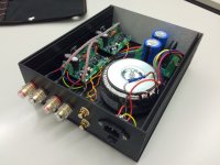
I've been running my Modulus-86 amp for a couple of weeks now, and so far I'm very happy with it. When I first posted pictures of my build, a few people suspected that I didn't have enough heat sink. What I can say is that I'm not experiencing any problems. After a few hours of use at reasonably high power, the heat sink on the chassis seems to stabilise at what I'm guessing is some 40 degrees Celsius i.e. kind of lurk-warm to the touch but nothing more. I even have both chips mounted on the same side of the chassis.
The only problem I'm facing is that the fuse blows if I turn on my pre-amplifier BEFORE turning on the Mod-86. If I turn on the Mod-86 first before any signal is seen on the inputs, the fuse is fine. I'm using a 1.6A slow fuse (240V). Can anyone suggest a solution?
Soren
Attachments
Hi guys,
I've been running my Modulus-86 amp for a couple of weeks now, and so far I'm very happy with it. When I first posted pictures of my build, a few people suspected that I didn't have enough heat sink. What I can say is that I'm not experiencing any problems. After a few hours of use at reasonably high power, the heat sink on the chassis seems to stabilise at what I'm guessing is some 40 degrees Celsius i.e. kind of lurk-warm to the touch but nothing more. I even have both chips mounted on the same side of the chassis.
The only problem I'm facing is that the fuse blows if I turn on my pre-amplifier BEFORE turning on the Mod-86. If I turn on the Mod-86 first before any signal is seen on the inputs, the fuse is fine. I'm using a 1.6A slow fuse (240V). Can anyone suggest a solution?
Soren
Hi Soren,
Two options, already discussed here: uprate the fuse or build a soft start circuit.
1.6A fuse is marginal for me on 240v UK mains but they work most of the time; This suggests that a slightly larger fuse should cope better, say 2A or 2.5A. The 1A fuses all immediately died and I had to wait for an order of 1.6 fuses then ordered some 2A for good measure.
I had three 1.6A fuses blow on the initial test but strangely since the initial test day the amplifier has been turned on several times a day and I am told by my Dad (I built it for him) that it hasn't blown another one yet. Also when he turns his system on everything comes on (all system components) and it is immediately playing the Radio as it warms up.
I have supplied him with the pack of 2A fuses.
So you could uprate the fuse anyway and decide if you want to build a soft start.
Last edited:
Hi Rob,
Thanks for your reply. I think I will update the fuse as a first measure and see how it goes.
Thanks for your reply. I think I will update the fuse as a first measure and see how it goes.
Regulated power supply rails for the LM3886
Tom and company,
Why? Because the main voltage of my home fluctuates between 230V and 242V.
For now, I use an AV Marantz SR4500. When voltage is 237V or more the sound becomes vulgar and unpleasant. Why I am interested in the regulation.
Tom and company,
After reading this old thread from 2005 I would like to ask your opinion on the subject of regulated power supply rails for the LM3886.
Any benefit to regulating Power Amp supply rails for LM3886?
Why? Because the main voltage of my home fluctuates between 230V and 242V.
For now, I use an AV Marantz SR4500. When voltage is 237V or more the sound becomes vulgar and unpleasant. Why I am interested in the regulation.
Last edited:
After reading this old thread from 2005 I would like to ask your opinion on the subject of regulated power supply rails for the LM3886.
The Modulus-86 has incredibly high power supply rejection ratio. You will not see any benefit of using a regulated supply.
A naked LM3886 will benefit greatly from a regulated supply.
Tom
Class AB with a Regulated Supply...Approaching Class A?
Dan Joffe:
Akitika Preamp and Power Amp Kits
A naked LM3886 will benefit greatly from a regulated supply.
Tom
Dan Joffe:
Akitika Preamp and Power Amp Kits
Class AB with a Regulated Supply...Approaching Class A?
The GT-101 has an electronically regulated power supply. That makes it unusual among audio power amplifers. But in some ways, it offers an advantage similar to class A operation.
Class A amplifiers can be among the most linear of amplifiers, and the least efficient. They draw a constant current from the power supply, no matter what signal is being delivered to the speaker. That says that a Class A amplifier doesn't modulate the supply rails..constant current drain produces a constant load on the power supply, and hence a constant voltage.
Is a Class AB amplifier with an electronically regulated power supply almost as good in that respect? If the power supply's output impedance is low, then the output signal minimally modulates the rails. That should cause less distortion at the output. In that sense, the Class AB with regulated power supply should be about as blameless as a Class A amp.
The one way that the Class A amplifier still has it over the Class AB is that at low listening levels, the output device has nearly constant current. That is, its operating current is the large class A bias current with the small signal modulations. Of course, at high output levels, the Class A advantage diminishes, as the output device then experiences wide swings in operating current.
This is wrong.They draw a constant current from the power supply, no matter what signal is being delivered to the speaker. That says that a Class A amplifier doesn't modulate the supply rails..constant current drain produces a constant load on the power supply, and hence a constant voltage.
Most ClassA amplifiers do modulate the supply rail current.
Only a very few ClassA topologies actually run as constant current when the output current changes, but they are rarely implemented.
- Home
- Amplifiers
- Chip Amps
- Modulus-86 build thread