The image is not displaying.
Try to right click on it and open in new card in your browser.
already been asked. will not happen.Dear Tom;
Can you put the stereo purchase option for Modulus 86 and do the Mirror finish PCB for L-R channels?
Try to right click on it and open in new card in your browser.
It's usually better to attach the images. That way they stay on the forum for everyone to see even after you delete them off your Google Drive. Click "Go Advanced" and then the attachment "paper clip" button. I've attached your image here.
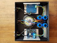
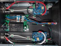
Nice and clean build. Well done! I like the use of aluminum angle extrusions to make a module out of the Modulus-86. Who else does that? 😉
You're very low on heat sinking; i.e. there isn't any, aside from the chassis itself. For a small desktop amp that'll never deliver more than 100 mW or maybe 1 W when really cranked, you're probably OK, but if you were to use the amp at a house party cranked to 11, the amp will overheat. With the amount of aluminum in those angle extrusions, it'll take some time to overheat, but it will get there. For short bursts at max power, the thermal mass of those extrusions will keep the amp happy as long as the average power is low.
I do like the idea of mounting the terminal blocks to the back side of the board as you did on the right channel. That's a neat trick for those who want a symmetrical build. Thanks for sharing.
Tom
Attachments
Can you put the stereo purchase option for Modulus 86 and do the Mirror finish PCB for L-R channels?
I'm curious what drives this need. Would you mind elaborating? What are you trying to accomplish with the mirrored PCBs? Are you going after this purely for aesthetic reasons or do you have a technical reason for pursuing this?
As mentioned above, I will not make a mirrored version of the Modulus-86 board as doing so would negatively impact performance. But if there is a technical reason or you're pursuing the mirrored version for a reason that I'm not aware of, there is the possibility that I could meet you half-way. Would placing all the connectors along one edge of the board be sufficient to meet your needs?
Tom
Last edited:
For the reference. Just another way of building Mod-86.
An externally hosted image should be here but it was not working when we last tested it.
Thanks. Tom.
Tio,
😱
Maybe my eyes are deceiving me but I would not connect chassis ground to the center of the transformer bolt (your yellow wires with brown heatshrink). This becomes especially concerning if the transformer center bolt becomes loose. If it does, you've lost chassis ground connection and that is dangerous. Perhaps I am conservative but I certainly don't want you to get hurt!
The chassis ground connection should be separate and isolated on the chassis and it is recommended to use a locknut.
Here is a good example, although, I would minimize the use of regular nuts and just use washers/tooth washers and locknuts. You want the lowest impedance pathway to ground.
Be careful!
Best,
Anand.
Last edited:
You would have better wire routing without flipping the left board upside down, so as having a neater looking amp when taking pictures or showing it off. With the Mod 86, the screw down terminals for wire connections are a pain to install if you flip the board upside down, unless you mount the terminals like Tiofrankenator did to the bottom of the board. In my case I am making three channel amps with a Mod686 and 2-Mod86 boards in them. The Mod86 will be stacked over each other on the right side and the Mod686 on the left side upside down with terminals mounted to the board bottom. Directions are based on looking from the rear of the amp. Mine are going in a 3U 330x300 minidisipante chasis so space is at a premium. It will be powering the top 3 drivers in an Lx-521 speaker.
Tom, based on the photo you reposted - and other like builds, I’m thinking it’s gotta be just the aesthetics of symmetrical wiring, and the theoretical sonic veils to be lifted from adopting same. Once the covers are in place, I tend myself to be less concerned with that.
Would have to agree with both the location of chassis ground and insufficient heat sinking. I used a very similar style of Modushop chassis (Galaxy or Slimline - can’t actually remember) for a Hypex classD build a couple of years go, but at full tilt, they produce far less heat to be dissipated.
Would have to agree with both the location of chassis ground and insufficient heat sinking. I used a very similar style of Modushop chassis (Galaxy or Slimline - can’t actually remember) for a Hypex classD build a couple of years go, but at full tilt, they produce far less heat to be dissipated.
You would have better wire routing without flipping the left board upside down, so as having a neater looking amp when taking pictures or showing it off.
Oh, I agree with that. But that's the only advantage I can think of. You'd completely shoot yourself in the foot on the PCB layout. You'd have to run the power supply traces past all the other pins on the LM3886 - so you'll have significantly higher supply impedance, which will impact performance. You'd also have a helluva time routing the other signals out from the LM3886, so now you're looking at 4-layer boards. All in exchange for someone going "oooh! shiny!". Meh. Not my cup of tea.
A good PCB layout involves much, much more than just connecting the dots.
What I can do is to put the connectors along one side of the board as I've done in the Modulus-186 and beyond. It still won't be a mirrored board, but at least the wire exits will look prettier. It'll grow the board (or make the board a 4-layer board), though. Is it worth the additional cost? Would you pay $10-20 more to have a board with the connectors along the edge?
With the Mod 86, the screw down terminals for wire connections are a pain to install if you flip the board upside down, unless you mount the terminals like Tiofrankenator did to the bottom of the board.
True that. The JST VH terminals I use on the Modulus-186 and -286 would be better for that. There's a 90º version of those that you could use that'd allow for horizontal wire entry and plugging/unplugging of the connectors with all boards mounted.
Tom, based on the photo you reposted - and other like builds, I’m thinking it’s gotta be just the aesthetics of symmetrical wiring, and the theoretical sonic veils to be lifted from adopting same.
I think that's the case too. However, creating a mirrored board would add veils for sure. So while you might think you're removing a veil with the pretty chassis wiring (I doubt the veil will be measurable) you'll be adding several (measurable!) veils by mucking up the PCB layout. I've made this point quite a few times now, so I'm a little perplexed that it still pops up. It makes me question whether there's some other reason that people would like a mirrored board that I'm just not aware of. Maybe I could make a board that would satisfy those needs without mucking up the performance. But I won't know until people tell me what they actually need. "Connectors that allow for better stacking of the boards" is a need that I can act on.
If "it looks pretty" is the reason, then the answer is a hard no. I won't muck up performance to make something look pretty. Sorry. That's not how I operate. 🙂
Once the covers are in place, I tend myself to be less concerned with that.
Me too. I'm far more concerned with input-to-output performance than any touchy-feely within the box.
Tom
I also tend to like mirror because of the looks, but it's an unnecessary complication. I think it's much easier to have a layout with both boards in one side on the box and cables would all be same length as well. You "only" have to make sure that side has a big enough heatsink.

Attachments

.....I won't muck up performance to make something look pretty. Sorry. That's not how I operate. 🙂.....
.....

Attachments
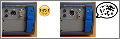
How much could a few more inches of carefully routed internal wiring that such layouts would eliminate possibly affect the measurable or audible performance?
As a lazy old bugger, I’m far past fabricating chassis for any amp builds from scratch, and on any future project would be buying something like the offerings from DIY Audio store/ HiFi2000. As the only piece I’ve ever seen from them with a single heatsink per enclosure was the original dual mono chassis ACA kit, and it just only makes sense to use both finned sinks to more evenly distribute the thermal dissipation load - to which the top and bottom cover also contribute.
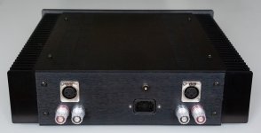
OTOH, I do like a symmetrical layout of back panel - and as I’m a huge fan of Pomona style dual binding posts, quite appreciate the effort Tom took to locate the 5-way binding posts on 3/4” centres on the Mod286 kit to facilitate their use. One of these days I’ll try to switch over to Speakons, but old habits (+40yrs) die hard.
As a lazy old bugger, I’m far past fabricating chassis for any amp builds from scratch, and on any future project would be buying something like the offerings from DIY Audio store/ HiFi2000. As the only piece I’ve ever seen from them with a single heatsink per enclosure was the original dual mono chassis ACA kit, and it just only makes sense to use both finned sinks to more evenly distribute the thermal dissipation load - to which the top and bottom cover also contribute.
OTOH, I do like a symmetrical layout of back panel - and as I’m a huge fan of Pomona style dual binding posts, quite appreciate the effort Tom took to locate the 5-way binding posts on 3/4” centres on the Mod286 kit to facilitate their use. One of these days I’ll try to switch over to Speakons, but old habits (+40yrs) die hard.
The uber-symmetrical wiring is not in any way rewarded with better performance, just to keep the OCD neurons from blinking away all night long.
How much could a few more inches of carefully routed internal wiring that such layouts would eliminate possibly affect the measurable or audible performance?
Any added wire will add impedance, which could impact performance. Same for adding trace length on the PCB. The choice (neglecting routing issues on the PCB) is basically a few inches of AWG 12 wire vs a few inches of PCB trace. The latter will always have higher resistance, thus degrade performance more than the former.
I have not been able to measure any impact of chassis wiring ... and I normally use AWG 16 pre-crimped leads.
As a lazy old bugger, I’m far past fabricating chassis for any amp builds from scratch, and on any future project would be buying something like the offerings from DIY Audio store/ HiFi2000.
As an entrepreneurial middle-aged (did I really just use that term to describe myself?!) bugger, I wholeheartedly agree with you. I don't see any reason to manufacture my own chassis. Basically for around 2x the cost of the raw materials, I can buy a fully manufactured chassis with a nice surface finish. If I'm willing to pay a bit more, I can even have it arrive with all the holes drilled and tapped.
OTOH, I do like a symmetrical layout of back panel
The outside of the chassis does need to be pretty.
I’m a huge fan of Pomona style dual binding posts, quite appreciate the effort Tom took to locate the 5-way binding posts on 3/4” centres on the Mod286 kit to facilitate their use.
Yeah. That was a fun little geometry exercise. 🙂
The uber-symmetrical wiring is not in any way rewarded with better performance, just to keep the OCD neurons from blinking away all night long.
Hmmm... Can we turn those neurons off with a central nervous system depressant, such as alcohol? That seems worth a try. 🙂

Tom
Indeed, I’m thinking that the bottle in front of him to which kevin’s signature line refers is not a fizzy sugar dosed soft drink. It’s now officially 5:00 PM in Maui, so time to get cracking on emptying that 1.5 litre - and I think that Aussie ginger beer is better than the Bermudian Barritts.
Under carefully monitored lab conditions, I think a little C2H6O can help - although I am thankful I no longer have to worry about hand cueing a vinyl rig outfitted with $2000 moving coil cartridge.
And I guess you’d need to have a good guess as to your personal life expectancy to judge the start date and duration of your own middle age.
Last edited:
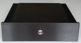
Modulus-86 / SMPS-86 completed
My first build was an LM3886-DR and Power-86. Although that went fine, I never managed to remove an irritating mains hum from the transformer (maybe as a result of a DC offset on the mains here in the UK) so wanted to try something different. This time I went for a Modulus-86 with an SMPS-86 power supply. The SMPS (at ±24V) will result in a slightly lower power than running the amplifier from a transformer / Power-86 for example, but this is destined as a desktop system so getting maximum power from the Modulus-86 wasn't essential. I did briefly consider the newly released Modulus-186, but I wanted to build this myself rather than buying a pre-constructed module. The Modulus-186 was also a little spendy for me at the moment...
The hope was that the SMPS-86 would be much quieter than the transformer / Power-86 combination. I built this first and on switching it on, aside from a small click from the relay, it is practically silent. All good so far.
Building the Modulus-86 boards took me some time. It is clearly a much more complex circuit that the LM3886-DR (just based upon the component count). My eyes aren't what they once were, so I found working in front of a window in natural light necessary (I'm not even all that old - but I've recently started to have to wear glasses, much to my dislike 🙁). Anyway, I took it slowly and enjoyed the process.
I purchased a Mini Dissipante chassis from ModuShop in Italy and while completing the electronics, passed the front and rear panels to a friend who has an mechanical engineering company. He did a much tidier job of the chassis cut-outs than I would have managed with hand-tools.
Before and during the build I exchanged emails with Tom a few times:
The chassis I ordered was on the slightly larger side - the next size down would have been a tight fit and I didn't want this to be a pain to work on. This means that the installation into the chassis was all very straightforward and I'm quite pleased how tidily it came out.
As for the result...
Well, firstly, the amplifier is completely silent with no signal. And nothing at all that I can hear from the speakers either. In this regard, it is much better than my previous build. So, that was a relief!
As for the audio quality, I'm no good when it comes to comparing these things. I think I'm hearing aspects of the music that I didn't hear before, but I'd be the first to admit that that could just be my imagination. I'm certainly very happy with the result though.
A few pictures of the finished amplifier attached.
My first build was an LM3886-DR and Power-86. Although that went fine, I never managed to remove an irritating mains hum from the transformer (maybe as a result of a DC offset on the mains here in the UK) so wanted to try something different. This time I went for a Modulus-86 with an SMPS-86 power supply. The SMPS (at ±24V) will result in a slightly lower power than running the amplifier from a transformer / Power-86 for example, but this is destined as a desktop system so getting maximum power from the Modulus-86 wasn't essential. I did briefly consider the newly released Modulus-186, but I wanted to build this myself rather than buying a pre-constructed module. The Modulus-186 was also a little spendy for me at the moment...
The hope was that the SMPS-86 would be much quieter than the transformer / Power-86 combination. I built this first and on switching it on, aside from a small click from the relay, it is practically silent. All good so far.
Building the Modulus-86 boards took me some time. It is clearly a much more complex circuit that the LM3886-DR (just based upon the component count). My eyes aren't what they once were, so I found working in front of a window in natural light necessary (I'm not even all that old - but I've recently started to have to wear glasses, much to my dislike 🙁). Anyway, I took it slowly and enjoyed the process.
I purchased a Mini Dissipante chassis from ModuShop in Italy and while completing the electronics, passed the front and rear panels to a friend who has an mechanical engineering company. He did a much tidier job of the chassis cut-outs than I would have managed with hand-tools.
Before and during the build I exchanged emails with Tom a few times:
- The Mouser BOM had some items out of stock, so Tom was able to suggest and confirm in-stock alternatives.
- Checking pin-outs on the SMPS board to use an external switch (the BOM includes a switch mounted to the SMPS board that I didn't want to use).
- Checking about using a dim-bulb tester with the SMPS-86 (short answer - it still serves a useful purpose, but given the lack of large capacitors, typically wont glow brightly before dimming).
The chassis I ordered was on the slightly larger side - the next size down would have been a tight fit and I didn't want this to be a pain to work on. This means that the installation into the chassis was all very straightforward and I'm quite pleased how tidily it came out.
As for the result...
Well, firstly, the amplifier is completely silent with no signal. And nothing at all that I can hear from the speakers either. In this regard, it is much better than my previous build. So, that was a relief!
As for the audio quality, I'm no good when it comes to comparing these things. I think I'm hearing aspects of the music that I didn't hear before, but I'd be the first to admit that that could just be my imagination. I'm certainly very happy with the result though.
A few pictures of the finished amplifier attached.
Attachments
Last edited:
that is a really nice build, congratulations. what's the exact Mini Dissipante width/depth size? thank you
that is a really nice build, congratulations. what's the exact Mini Dissipante width/depth size? thank you
It is this one:
Mini Dissipante 2U 300mm 10mm BLACK front panel - 2mm aluminium covers and 3mm rear panel
Internal dimensions 250mm wide by 300mm deep.
It is this one:
Mini Dissipante 2U 300mm 10mm BLACK front panel - 2mm aluminium covers and 3mm rear panel
Internal dimensions 250mm wide by 300mm deep.
thank you!
- Home
- Amplifiers
- Chip Amps
- Modulus-86 build thread