There's a vendor on eBay 'nooelec' from whom I've purchased muMetal (the brand name he sells is 'Ultraperm'). It comes in 8" x 10.5" sheets with 3M PSA adhesive on the back. A quick check of eBay indicates he has stock available.
Genuine MuMetal from Magnetic Shield Corp. can be purchased through Digi-Key and seems to be in stock. We've purchased this at the office; order from D-K and shipped from Magnetic Shield Corp.
Genuine MuMetal from Magnetic Shield Corp. can be purchased through Digi-Key and seems to be in stock. We've purchased this at the office; order from D-K and shipped from Magnetic Shield Corp.

I’ve never used these but it sounds like I should start doing ! A question though; are the ferrules and the related crimping tools all a standard design / fit, or is it one of those things where every manufacturer uses a slightly different design to try and lock you in to their products?Other things I consider mandatory on the build: Boot lace ferrules. I picked this up from Tom's video. I'll never use bare wire again, you get a much more secure connection using crimps. There are 'HiFi' versions of crimps as well in pure copper, that aren't that expensive to use in the signal path.
They’re universal - I just bought a ferrule crimp kit off eBay, then for key parts in the signal chain I purchased some wtb ones.I’ve never used these but it sounds like I should start doing ! A question though; are the ferrules and the related crimping tools all a standard design / fit, or is it one of those things where every manufacturer uses a slightly different design to try and lock you in to their products?
I, too, bought a kit off ebay that appears to be well made and pretty universal. Curiously, one of the European connector companies, whose ferrules you can buy from Digi-Key, points out in their literature that there is an IEC standard that recommends ('requires'?) that one should only crimp ferrules with the 'proper' tool sold by the manufacturer of the ferrules. That gives the choice of an affordable ~$20 Chinese tool off Amazon (that comes with a pile of ferrules as part of the kit) or following the standard and buying the virtually identical $400 tool from a German brand name. For us mere DIYers, the choice seems obvious.
I don’t think you can go wrong - unlike some crimps boot lace ferrules are really easy to tell that you’ve got a good crimp. Cheap kit off eBay/Amazon is fine and worth the effort for security of connection.I, too, bought a kit off ebay that appears to be well made and pretty universal. Curiously, one of the European connector companies, whose ferrules you can buy from Digi-Key, points out in their literature that there is an IEC standard that recommends ('requires'?) that one should only crimp ferrules with the 'proper' tool sold by the manufacturer of the ferrules. That gives the choice of an affordable ~$20 Chinese tool off Amazon (that comes with a pile of ferrules as part of the kit) or following the standard and buying the virtually identical $400 tool from a German brand name. For us mere DIYers, the choice seems obvious.
Great build.686 build complete... Will post review / comparisons in due course.
Is it review/comparisons time yet ???
Best amp I’ve owned. There are a couple of options out there that might provide something slightly different, but not likely better per say. PM me if you want to discuss further.Great build.
Is it review/comparisons time yet ???
That was where I landed as well. If I was building aircraft or space shuttles I might have a different opinion, but I build amps... 🙂That gives the choice of an affordable ~$20 Chinese tool off Amazon (that comes with a pile of ferrules as part of the kit) or following the standard and buying the virtually identical $400 tool from a German brand name. For us mere DIYers, the choice seems obvious.
I bought my ferule kit from Bezos' Bookstore for something like $25 USD. The kit came with the tool.
Tom
And you'd have to use transparent heat shrink so that every single crimp and solder joint can be inspected. Hundreds of thousands in a typical space vehicle.That was where I landed as well. If I was building aircraft or space shuttles I might have a different opinion, but I build amps... 🙂
Tom
It is all mind-numbing detail. I speak as project manager for an instrument on board this https://sci.esa.int/web/bepicolombo . The exciting bit is developing the instrument. It then gets increasingly deathly boring when it gets to building the flight model that is going to fly.
The instrument that I was responsible for is nothing like as complex as Webb, and my heart goes out to those who had to deal not only with developing the massively complex machine, but dealing with the political fall out too when it overspent massively.
All very far from domestic audio - which is always fun!
Hi All!,
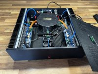
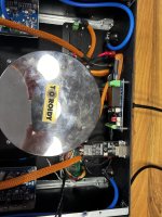
I recently finished my build around Modulus-686, finally after almost 2 years 🙂
I built a stereo version based "Safe-n-Sane" Build as described in Neurochrome website, to have about 100w per channel using 500VA Transformer with 2x22 VAC. The amp is configured to have 20db gain. (lowest setting I believe)
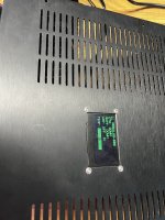
I also built at custom Board with an STM32F4 MCU to be able to control the amplifier via Ethernet and integrate it wit Home-Assistant software via MQTT. I can also monitor the temperatures of the Heatsinks using an NTC.
Main parts used:
2 x Neurochrome Modulus-686
1 x Neurochrome Power-686
1 x Neurochrome Intelligent Soft Start
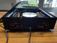
1 x Toroidy 500VA 2 x 22 VAC SUPREME AUDIO grade transformer (TSAS500VA)
1 x Custom made board with STM32F407VET6 MCU
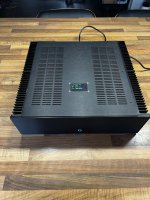
1 x Modushop Dissipante 3U 400mm
I'm planning to pair it with an Arcam ST60 Digital DAC/Preamp.
So far I'm pretty help with build and all support given by Tom 🙂 I like the sound the a lot, but I'm planning to upgrade my current Monitor Audio Bronze to an LS50 Meta in near future. Maybe if it was now I would chose a smaller Toroidal transformer as this one taking a quite a lot of real state inside the case.
I also had to learn a lot about electronics, MCUs and develop my soldering skills. That's why it took so long!
Now I'm just improving the firmware of the MCU so I can add more functionality and configuration, i.e. the possibility to chose the color when amp on and off (completely useless I know 🙂 )
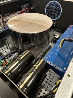
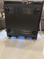
I'm sharing some photos as well!
Please let know if you have some feedback or suggestions for improvements!
Thanks all and happy builds!!!
Leandro
I recently finished my build around Modulus-686, finally after almost 2 years 🙂
I built a stereo version based "Safe-n-Sane" Build as described in Neurochrome website, to have about 100w per channel using 500VA Transformer with 2x22 VAC. The amp is configured to have 20db gain. (lowest setting I believe)
I also built at custom Board with an STM32F4 MCU to be able to control the amplifier via Ethernet and integrate it wit Home-Assistant software via MQTT. I can also monitor the temperatures of the Heatsinks using an NTC.
Main parts used:
2 x Neurochrome Modulus-686
1 x Neurochrome Power-686
1 x Neurochrome Intelligent Soft Start
1 x Toroidy 500VA 2 x 22 VAC SUPREME AUDIO grade transformer (TSAS500VA)
1 x Custom made board with STM32F407VET6 MCU
1 x Modushop Dissipante 3U 400mm
I'm planning to pair it with an Arcam ST60 Digital DAC/Preamp.
So far I'm pretty help with build and all support given by Tom 🙂 I like the sound the a lot, but I'm planning to upgrade my current Monitor Audio Bronze to an LS50 Meta in near future. Maybe if it was now I would chose a smaller Toroidal transformer as this one taking a quite a lot of real state inside the case.
I also had to learn a lot about electronics, MCUs and develop my soldering skills. That's why it took so long!
Now I'm just improving the firmware of the MCU so I can add more functionality and configuration, i.e. the possibility to chose the color when amp on and off (completely useless I know 🙂 )
I'm sharing some photos as well!
Please let know if you have some feedback or suggestions for improvements!
Thanks all and happy builds!!!
Leandro
Attachments
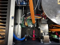


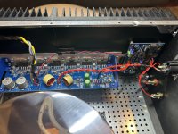
Great looking build! What are the large white connectors on the PCBs? They appear to be mating parts with one connector soldered to the PCB, and the other plug in/pull out. What company and model/series are these?
Thank you!
Not sure exactly what you mean? Which photo?
Great looking build! What are the large white connectors on the PCBs? They appear to be mating parts with one connector soldered to the PCB, and the other plug in/pull out. What company and model/series are these?
Not sure exactly what you mean? Which photo?
https://neurochrome.com/products/mo...66694&pr_ref_pid=4097695744070&pr_seq=uniformWhat are the large white connectors on the PCBs? They appear to be mating parts with one connector soldered to the PCB, and the other plug in/pull out. What company and model/series are these?
JST VL series
Poseidon‘s Voice Neurochrome Modulus 686 build
Well I guess it’s high time I join the Modulus 686 club as well. In all honesty, I’ve had these boards for roughly three years and had it all hooked up to a pair of spare heatsinks with test leads and a generic PS. Listened to it for a few days…and to my surprise I had a hard time pulling away, it literally sucked the mojo out of my amp building passion hence…I shut it off and postponed the build…until now.
Ingredients
What I’m basically saying (to the newbies reading this thread) is that my method of building is somewhat overdone and downright silly when you look at the prowess of the 686 as a design. It has a PSRR that is beyond reproach and is a balanced composite design with a differential input so all these ‘extras’ are really just that…gilding the lilly.
One can pretty much get superlative performance with Tom’s recommendation of using a well designed MeanWell switcher supply and not worry about power supply boards, ISS, etc…because the Modulus 686 as a design doesn’t care. It’s power supply agnostic. If you feel threatened by the switcher supply, then do this. Load the top with pretty looking granite (away from the vent holes) and voila, your switcher amp is ‘heavy’ and therefore…’mo betta 😉 .
Perusing this thread, I am humbled by the builds of @pinnocchio, @sledwards12375, and @stretchneck. My build is very much average with little innovation to be honest. The only part that really tickled my fancy was the implementation of the capacitive touch switch!
On it’s maiden voyage the amp fired up to +/- 35V and dc offset on the binding posts was <1mV all within a few seconds. This is a no brainer design.
Alright, y’all have read enough, it’s time to throw in some pics. As always, I‘ll rotate back with some initial sonic observations and comparisons in the near future. Kudos and thanks to @tomchr for all he has taught and all he will teach me. And yeah, a reference in Class AB designs.
Pics


Well I guess it’s high time I join the Modulus 686 club as well. In all honesty, I’ve had these boards for roughly three years and had it all hooked up to a pair of spare heatsinks with test leads and a generic PS. Listened to it for a few days…and to my surprise I had a hard time pulling away, it literally sucked the mojo out of my amp building passion hence…I shut it off and postponed the build…until now.
Ingredients
- Customized Modushop 4U/400 Dissipante Chassis
- Customized Toroidy Audio Supreme v2 800VA transformer with quad 25VAC secondaries and a single 120V primary
- Neurochrome ISS v1.1 board (customized for the capacitive switch)
- Schurter capacitive multicolor touch switch
- Pair of Neurochrome Power 686 boards each with (4) 22mF Mundorf 63VDC capacitors
- Pair of Neurochrome Modulus 686 boards
- Pair of Neurochrome Guardian 686 boards
- Ground Lift & T-GND boards
- Furutech XLR, Furutech binding posts, and Furutech IEC
- Wires of various gauges from Neotech and generic mil-spec wire
What I’m basically saying (to the newbies reading this thread) is that my method of building is somewhat overdone and downright silly when you look at the prowess of the 686 as a design. It has a PSRR that is beyond reproach and is a balanced composite design with a differential input so all these ‘extras’ are really just that…gilding the lilly.
One can pretty much get superlative performance with Tom’s recommendation of using a well designed MeanWell switcher supply and not worry about power supply boards, ISS, etc…because the Modulus 686 as a design doesn’t care. It’s power supply agnostic. If you feel threatened by the switcher supply, then do this. Load the top with pretty looking granite (away from the vent holes) and voila, your switcher amp is ‘heavy’ and therefore…’mo betta 😉 .
Perusing this thread, I am humbled by the builds of @pinnocchio, @sledwards12375, and @stretchneck. My build is very much average with little innovation to be honest. The only part that really tickled my fancy was the implementation of the capacitive touch switch!
On it’s maiden voyage the amp fired up to +/- 35V and dc offset on the binding posts was <1mV all within a few seconds. This is a no brainer design.
Alright, y’all have read enough, it’s time to throw in some pics. As always, I‘ll rotate back with some initial sonic observations and comparisons in the near future. Kudos and thanks to @tomchr for all he has taught and all he will teach me. And yeah, a reference in Class AB designs.
Pics
Last edited:
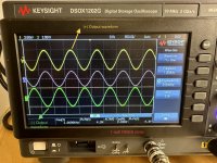
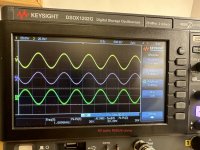
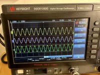
Some more pics and measurements attached. Don’t worry, me and my alter ego are arguing about the pin 1 issue. It will be resolved 😉  .
.
Best,
Anand.
.Best,
Anand.
Attachments
-
 IMG_9757.jpeg602.8 KB · Views: 233
 -
 IMG_9754.jpeg541.3 KB · Views: 232
 -
 IMG_9764.jpeg561.5 KB · Views: 216
 -
 IMG_9767.jpeg536.6 KB · Views: 212
 -
 IMG_9768.jpeg554.2 KB · Views: 200
 -
 IMG_9773.jpeg518.3 KB · Views: 192
 -
 IMG_9760.jpeg340.2 KB · Views: 214
 -
 IMG_9758.jpeg539.4 KB · Views: 224
 -
 IMG_9755.jpeg626.9 KB · Views: 226
Last edited:
- Home
- Vendor's Bazaar
- Modulus-686: 380W (4Ω); 220W (8Ω) Balanced Composite Power Amp with extremely low THD