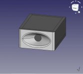
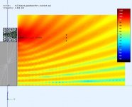
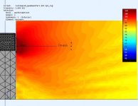
The literature on the $60K Magico Q5 with TMWWW topology should interest you. A simple baffle diffraction simulation illustrates the reduced distortion from the large radius edge rounds.
Type: Four-way, five-driver, sealed-enclosure, floorstanding loudspeaker
Driver complement: Two 9" woofers, one 9" mid/bass, one 6" midrange, one 1" tweeter
Sensitivity: 86dB 1w/1m
Impedance: 4 ohms, 2.75 ohms min.
Frequency response: 18Hz-50kHz +/-3dB
Minimum amplifier power: 50W
Dimensions: 11.8" x 47" x 12.5"
Weight (net): 420 lbs. each
Price: $60,000/pair
“As a work of industrial art, the Magico Q5 is beautiful...When you first listen to it, the Q5 may also sound uninvolving because it has little or no personality of its own. But in a loudspeaker, that's what you want. The longer I listened, the more I appreciated the Q5's ability to get out of the way and let the recording's own personality assert itself.”
— Michael Fremer, The Absolute Sound
Magico Q5 Loudspeaker (TAS 214) | The Absolute Sound
May I ask if putting woofers or mids in a recessed design with nice smooth curves helps? Im designing my cab in CAD for full CNC/Mill so I could easily implement it.
Is there a theory behind it? (similar to the baffle edge shape)
In my sims for just the quad woofers, I don't see any artifacts from the sharp cutout edges. I was surprised that the MF sim shows diffraction from sound travelling down the cabinet length then off the 4 woofer edges. I should try rounding the woofer cutouts to see if it helps. Any rounding helps in the MF and HF regions and there is no downside (except expense) from rounding. The curved front of the Q5 would help and I sim'd curved
baffle surfaces earlier in this thread.
baffle surfaces earlier in this thread.
.. more floor bounce
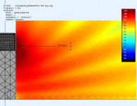
I tried a sim to limit the vertical MF energy hitting the floor. I placed the 2" dome into an impromptu "waveguide" and the speaker is on a carpet. An improvement but I still have some residual floor bounce and diffraction from the woofer edges but it's better. I should try with a proper horn / waveguide and round out the woofer edges.
I tried a sim to limit the vertical MF energy hitting the floor. I placed the 2" dome into an impromptu "waveguide" and the speaker is on a carpet. An improvement but I still have some residual floor bounce and diffraction from the woofer edges but it's better. I should try with a proper horn / waveguide and round out the woofer edges.
Attachments

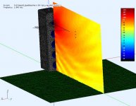
MF horn floor bounce
This sim is with a proper horn.
The horn profile was generated by @docali using the spherical horn calculator DrBA horns at sphericalhorns.net . This spherical horn has fc=425Hz, Lamé exp=8, sin based stretch factor 1.94 and no projection (ie. flat mouth).
I have mounted the horn in a simple case and elevated it using an ABEC shell cabinet. The replacement woofer cabinet is the same size as the earlier quad woofer cabinet but it's faster to simulate 🙂
Pic#1,2,3,4 shows the horn in 4Pi space, the wavefronts are spherical with some minor effects from the lower cabinet. I would also get the same minor effects from an upper tweeter cabinet.
Pic#5 is 2Pi space (ie. concrete floor) and has floor reflections but maybe the nulls are not as pronounced as before.
Pic#6,7 is 2Pi space with a carpet, and there are subdued reflections but it's the best wavefront so far. At 2m the field is nearly uniform.
Best of all,.... it's starting to look like an Inukshuk 🙂
Attachments
-
 2Pi_rug_Vfield@2KHz.jpg39.2 KB · Views: 128
 -
 2Pi_rug_QuadWooferStand+swh425.jpg52.9 KB · Views: 137
 -
 2Pi_field@2KHz.jpg42.9 KB · Views: 135
 -
 4Pi_Vfield@2KHz.jpg39.3 KB · Views: 126
 -
 4Pi_Hfield@2KHz.jpg37.8 KB · Views: 137
 -
 swh425.jpg66.6 KB · Views: 456
 -
 QuadStand_SWH425hornjpg.jpg60.4 KB · Views: 440
What a great thread! Your speaker setup reminds on a project recently published in a German speaker DIY magazine. The horn you used has a rather drastic stretch factor which may be a benefit reducing reflections as the vertical axis is more narrow. I can only say that you are the master of ABEC sims!
I agree, the narrow vertical is helping here. I think the horn itself also helps as it couples to air better than a cone/dome driver.
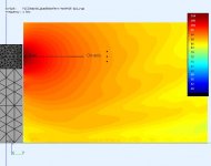
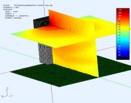
... MF cone and floor bouce
I also tried a 5" midrange cone to see how it performs. It's modeled after Dayton RS125p which is not a strict midrange but it goes high enough and is supplied with enough data to model it.
Although vertically wider than the previous spherical horn, it's narrow compared to a 2" dome. It's not too bad if a rug or carpet is in front of it.
Pic#1 is the model on a carpet.
Pic#2 is the vertical field on a carpet
Pic#3 is the horizontal field showing floor bounce effect
Attachments

Don, midranges typically play much lower - how about 300Hz, 600Hz, 1200Hz?
5"er starts to beam above 2kHz - SEAS CA15RLY

5"er starts to beam above 2kHz - SEAS CA15RLY
Last edited:
Hi @juhazi
There is a chart in post#4 showing radiation angle vs driver size Modular active 3 way - work in progress
I have simulations for a range of frequencies but only post a few graphs. The problem with the lower frequencies (300Hz) is that the carpet is less effective at attenuating these. I've attached the 5" driver graph for 1Khz to show that the carpet attenuation is less effective and it will only get worse with lower freq. I would have to rerun the 5" midrange simulation to get freq. samples at <1Khz . So I tried to solve the lower range (100Hz-725Hz) using a short woofer stack.Modular active 3 way - work in progress
My XO is hardwired midrange 725-4550Hz so that I can use domes, horns, and cones. It also avoids an XO in a region the ear is the most sensitive (Fletcher-Munson).
Attachments
May I ask if putting woofers or mids in a recessed design with nice smooth curves helps? Is there a theory behind it? I'm designing my cab in CAD for full CNC/Mill so I could easily implement it.
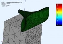
I would not build a baffle with recessed drivers. I would maintain enough flat baffle width to counter-sink and front mount the speakers, and then start machining the large radius rounds. Ending up with a wider cabinet baffle, or smaller radius rounds.
-----
I think Magico designers accepted a recessed driver baffle mounting because: (1) management wanted both a narrow cabinet and smooth large radius edge rounds, and this requires recessed drivers; (2) their custom drivers must be screwed into the rear of the baffle to maintain an ultra-smooth front baffle; (3) Magico invented a way to reduce driver resonance vibrations by mounting the woofer drivers at different angles on slanted baffle sections, and using recessed drivers supports this; (4) measurements and listening tests showed only minor distortion when the recess edges around the driver were also rounded.
a bit off topic but: @ Line Source. Could you show links to (third party) measurements of the Magico's?
TBH I always have the feeling Magico is more into the Massive Cost No Objective Hardware approach than into intelligent multiway system integration. But that is just an opinion.
TBH I always have the feeling Magico is more into the Massive Cost No Objective Hardware approach than into intelligent multiway system integration. But that is just an opinion.
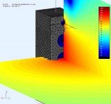
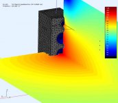
baffle roundness #1
I had a change to look at some of the concepts in the the Magico reference Modular active 3 way - work in progress
The first is my planned woofer stack (4 x 6.5") in a simple box with R-16mm rounding on the box edge. Woofers sit flush with the front. Simulation is in 4Pi space.
I had a change to look at some of the concepts in the the Magico reference Modular active 3 way - work in progress
The first is my planned woofer stack (4 x 6.5") in a simple box with R-16mm rounding on the box edge. Woofers sit flush with the front. Simulation is in 4Pi space.
Attachments
Last edited:
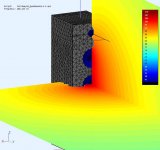
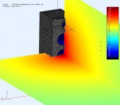
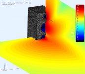
baffle roundness #2
Now applying the industrial design from the Magico to my quad 6.5" woofers stack. These sims are in 4Pi space.
There is a minimal reduction in edge diffraction from the additional rounding. Keep in mind this is for the woofer section and I would not expect much change because the wavelengths are still big.
Interesting, if the woofer is recessed it changes the dispersion (polar) characteristic like a shallow psuedo waveguide. I think mine are exaggerated because I recessed them 2-2.5cm from the curved baffle. This narrowing is starting to show at 900Hz which is probably high for a typical 3-way's woofer.
Attachments
Last edited:
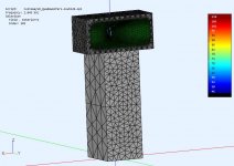
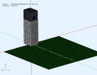
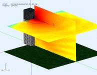
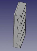
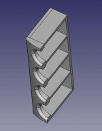
Quad woofers
I build the quad woofer cabinet, based on the sim from Modular active 3 way - work in progress to see I could tell the difference with less mid bass floor bounce.
The woofers were tested (pic#2) separately in their 9L chambers. These are still budget woofers (TC6028, WP6020) and the 9L chamber results in Qtc=0.9 which is higher than I'd like but fits the space I wanted to put it in. The consequence is a sloped FR which I will EQ out later. One of the woofers has a small problem with voice coil friction (minor sticking). It was mostly freed up after exercising it but still has reduced bandwidth.
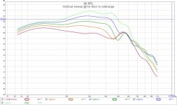
A vertical stepped FR sweep (pic#3) was measured at 1m distance, indoors and on a rug, with gating 2/10ms. It basically shows what the simulation indicated. The midbass is fairly even but louder as you get near the floor. You can also tell its more even as you move around. Now for some listening. 🙂
I build the quad woofer cabinet, based on the sim from Modular active 3 way - work in progress to see I could tell the difference with less mid bass floor bounce.
The woofers were tested (pic#2) separately in their 9L chambers. These are still budget woofers (TC6028, WP6020) and the 9L chamber results in Qtc=0.9 which is higher than I'd like but fits the space I wanted to put it in. The consequence is a sloped FR which I will EQ out later. One of the woofers has a small problem with voice coil friction (minor sticking). It was mostly freed up after exercising it but still has reduced bandwidth.
A vertical stepped FR sweep (pic#3) was measured at 1m distance, indoors and on a rug, with gating 2/10ms. It basically shows what the simulation indicated. The midbass is fairly even but louder as you get near the floor. You can also tell its more even as you move around. Now for some listening. 🙂
Attachments
Last edited:
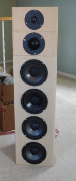
Inukshuk
The short woofer stack provides very even and clean bass and mid-bass in the room.
Now for the mid and high treatments using horns "like" the sim in Modular active 3 way - work in progress The tweeter is a Fane-CD130 + Dayton H07E and the midrange is PRV-D290PyB + B52-SH402. The SH402 is cheap and goes low enough to try for this experiment. I would prefer a midrange horn shaped more like the H07E.
It's eq'd for the FR flatish sloped and the voice coils are nearly aligned by shifting the boxes.
Attachments
Thanks Tony. The speaker seems to be growing 🙂
hehehe yes it does!! 😉 but so is your (and others reading this thread) knowledge!! 🙂
Last edited:
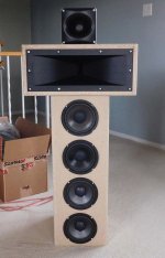
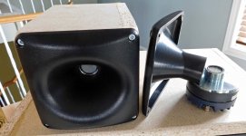
HF horn tests - FaneCD130 + Dayton H07E
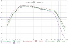
These are some measurements for the Fane CD130 with Dayton H07E horn. I wanted to compare them to the previous tweeters I measured.
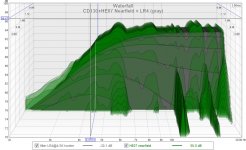
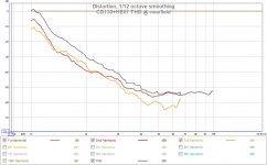
The CSD waterfall has the ideal LR4 filter (grey) included for comparison. I have some resonance points at [11.4K, 16K, 19.9KHz] . Not sure if they are from driver's titanium diaphragm or the plastic ringing. I don't notice them when listening. I'll probably investigate later.
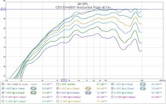
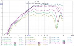
The horn is advertised 80x50deg and my measurements (0-50deg, 10deg step) tend to agree. My tests were indoors gated [-1,3ms] and taken with no baffle around the H07E horn as shown.
It sounds very clean and detailed.
These are some measurements for the Fane CD130 with Dayton H07E horn. I wanted to compare them to the previous tweeters I measured.
The CSD waterfall has the ideal LR4 filter (grey) included for comparison. I have some resonance points at [11.4K, 16K, 19.9KHz] . Not sure if they are from driver's titanium diaphragm or the plastic ringing. I don't notice them when listening. I'll probably investigate later.
The horn is advertised 80x50deg and my measurements (0-50deg, 10deg step) tend to agree. My tests were indoors gated [-1,3ms] and taken with no baffle around the H07E horn as shown.
It sounds very clean and detailed.
Attachments
- Home
- Loudspeakers
- Multi-Way
- Modular active 3 way - work in progress