It looks like emulating the EAR834 RIAA using a 750K resistor along with a 110pf and 330pf is a step in the right direction. I personally like the bass bump this curve (and the EAR834 clone itself) has, but if that bothers you, lower the 750K down to 732 with a 105pf appears to flatten it some. I do like the sound of mica caps in this network.
Also in my experience sometimes what looks best doesn't always sound best, especially from a sim, so I would experiment and listen.
Also in my experience sometimes what looks best doesn't always sound best, especially from a sim, so I would experiment and listen.

From post #73
This looks the best to me:
View attachment 1344917
732k resistors are available (e.g., https://www.digikey.com/en/products/detail/yageo/MFR-25FBF52-732K/13688)
If you want to use resistors you already have,
You can put a 680k and a 51k resistor in series to get 731k, which would be plenty close enough.
Or series up a 511k and 221k to get 732k.
Note that the 10pF cap is changed to 4.7pF.
@rongon
If one have bought the Little Bear kit there are a few more parts to change than just adjusting the RIAA feedback circutry.
Some more important than others. Output cap can be changed to something bigger if output have a lower resistance load.
Bass rolloff is set by the 0.1uF so output cap can be increase quite much without effecting RIAA tracking.
732kOhm is a standard value in E96 series which most supplier have.
Same if you go with the original EAR834P emulation. More than just the 750kOhm resistor that needs to be changed.
Friend of mine with a very high end system settled with the original EAR834P with transformers for MC.
Very, very good sound from the original.
Last edited:
Just out of curiosity, when you did these simulations and looked at their frequency responses, did you apply a load to the circuit? I look at the circuit with a load on it of 10k (simulating contemporary solid state amp volume controls), 50k (simulating older solid state amps), and 100k (simulating tube line amp volume controls). The low end is going to be different with all of those, so either one needs to optimize the circuit for the particular load to be expected, or massage the circuit values to work well enough for any load the preamp is likely to see.
Also, in simulation at least, increasing the output cap (1uF) to 4.7uF actually reduced the output from below 20Hz up to about 100Hz. It looks like the output cap, being inside the feedback loop, influences how much gain there is available for feedback. That makes this a pretty touchy circuit. Changing parts values seems to change the response quite a bit. That's not usually considered a positive attribute, because it implies that varying tube parameters will also change the response quite a bit. The frequency response is likely to change as the tubes age.
I came up with these changes. The response looks like it should stay the same into 10k, 50k and 100k ohm loads, with only a slight drop in output into 10k. There's a small bump in the low bass centered around 35Hz, but the forecasted response there is only +0.15dB above the output at 1kHz. Otherwise the response is forecasted to be very flat (+0.05dB at 100Hz, then within 0.01dB from 200Hz to above 20kHz). Of course the frequency response of the cartridge will change that, and the Miller capacitance of the input stage will also change the frequency response a bit. The input stage 12AX7 is not inside the feedback loop, so its Cmiller will be that of an unbypassed 12AX7, about 100pF or so, in addition to any tonearm cable and input wiring capacitances.
But these look to be exceedingly small differences. I'd like to build one of these and see if I like it as much as everyone else seems to. I've never heard any kind of 834P, original or clone. I think I'd build it with Tim de P's original values first.
Last edited:
@rongon
Yes, I loaded them according to schematics.
62K for Little bear
270K for original EAR834P
270K for my adjusted version.
And yes it's easy to change a bit here and there to get a better result during simulation.
ECC81 is also a better cathode follower for this circuit since it can handle more current. Not much of difference in sonic signature between ECC83 and ECC81 cathode follower.
Thus it should be no problem to load it with 100K instead of 270K as the original.
Less change in frequency response once connected to a preamp.
Select output cap size accordingly.
I would select a preamp with no less than 50kohm input impedance to not stress to much.
I fetched up the circuitry of my audio friends EAR834P and he had his modified from 1uF to 2,2uF for output cap and let the 270kohm fixed load remain.
Your curve seems dramatic, but it's actually just a 0,15 dB rise at 20 Hz.
A rise at 20 Hz of 1 dB or so will probably not be detected.
Linearity from 50-20000 Hz is where linearity matters most, so getting inside +/-1dB at 20 Hz is in my eyes good enough.
50-20000 Hz I would aim for as linear as possible but would be very satisfied with +/-0,25dB in real life.
Last edited:
The graph I posted is really zoomed in. Each horizontal line is only a 0.02dB step. The entire graph is well within 0.5dB.
By varied loads I meant the volume control you're likely to find on the input of the line stage after the phono preamp. That volume control's input impedance will appear in parallel with the pulldown resistor on the output of the phono preamp, which means it doesn't matter much what value that pulldown resistor is, the volume control's input impedance will likely define the load. Like in this input stage for an SE power amp I scrounged off the innerwebs:

The input impedance of that volume control will be 100k ohms, which will be the load presented to the phono preamp driving it.
That 100k ohm input impedance will be in parallel with the value of the pulldown resistor on the output of the source preamp.
If there's a 62k ohm pulldown resistor, and the input impedance of the load (driven stage) is 100k ohms, that will make the load on the phono preamp's output those two in parallel, or 62k*100k/62k+100k = 38.3k ohms.
If that volume control was only 5k ohms (as in some class D amps these days), that would be 62k*5k/62k+5k = 4.63k ohms
That's an 8 to 1 difference!
A 12AX7 cathode follower will have an output impedance of something like 1k ohms. The 220R build out resistor (on the output of the preamp) will add to that, so the Zout is 1250 ohms.
Into a class D amp with 5k ohm input impedance (yes, some are that low), that means the 12AX7 cathode follower is running into a load that's less than a 4:1 load:source impedance ratio. We'd like to see 10:1, so that 5k volume control is going to load down the 12AX7 cathode follower quite a bit.
A 12AT7 cathode follower will have an output impedance of somewhere around 250 ohms. Add the 220R build out resistance to that and the Zout is still less than 500 ohms. That will still get us close to our desired 10:1 load:source ratio even into that really low 5k ohm volume control.
That's why I like the idea of a 12AT7 cathode follower on the output, and why the pulldown resistor should be fairly large (if possible).
That's also why the output cap should be a higher value than 1uF, but that's a simple frequency response issue, which is a different matter.
Please feel free to critique my thinking here, and let us know if I'm misguided. Thanks.
By varied loads I meant the volume control you're likely to find on the input of the line stage after the phono preamp. That volume control's input impedance will appear in parallel with the pulldown resistor on the output of the phono preamp, which means it doesn't matter much what value that pulldown resistor is, the volume control's input impedance will likely define the load. Like in this input stage for an SE power amp I scrounged off the innerwebs:
The input impedance of that volume control will be 100k ohms, which will be the load presented to the phono preamp driving it.
That 100k ohm input impedance will be in parallel with the value of the pulldown resistor on the output of the source preamp.
If there's a 62k ohm pulldown resistor, and the input impedance of the load (driven stage) is 100k ohms, that will make the load on the phono preamp's output those two in parallel, or 62k*100k/62k+100k = 38.3k ohms.
If that volume control was only 5k ohms (as in some class D amps these days), that would be 62k*5k/62k+5k = 4.63k ohms
That's an 8 to 1 difference!
A 12AX7 cathode follower will have an output impedance of something like 1k ohms. The 220R build out resistor (on the output of the preamp) will add to that, so the Zout is 1250 ohms.
Into a class D amp with 5k ohm input impedance (yes, some are that low), that means the 12AX7 cathode follower is running into a load that's less than a 4:1 load:source impedance ratio. We'd like to see 10:1, so that 5k volume control is going to load down the 12AX7 cathode follower quite a bit.
A 12AT7 cathode follower will have an output impedance of somewhere around 250 ohms. Add the 220R build out resistance to that and the Zout is still less than 500 ohms. That will still get us close to our desired 10:1 load:source ratio even into that really low 5k ohm volume control.
That's why I like the idea of a 12AT7 cathode follower on the output, and why the pulldown resistor should be fairly large (if possible).
That's also why the output cap should be a higher value than 1uF, but that's a simple frequency response issue, which is a different matter.
Please feel free to critique my thinking here, and let us know if I'm misguided. Thanks.
No critique from my side 🙂
You have the necessary knowledge to make your own choices of design.
Regarding output cap, I would spend my money on a really good 2,2uF foil capacitor instead of a metallized 5-10uF capacitor even if it cut of deepest bass half a dB or so.
This circuit deserves good caps and resistors.
You have the necessary knowledge to make your own choices of design.
Regarding output cap, I would spend my money on a really good 2,2uF foil capacitor instead of a metallized 5-10uF capacitor even if it cut of deepest bass half a dB or so.
This circuit deserves good caps and resistors.
Is it worth buying one of these Little Bear preamps and modding it, or are there so many problems with it that it's better to start out with one of those EAR 834P PCBs and build up your own preamp from scratch?
Hello all little bear owners, please, I have a request, I put together a broken (total scrap) Little Bear T11 and I have three nylon washers left.
I don't know where to use them? Does the case have to be isolated from the PCB?

When measuring, the case is now connected to the signal ground, is that okay?
Thanks for the answer.
Jan
I don't know where to use them? Does the case have to be isolated from the PCB?
When measuring, the case is now connected to the signal ground, is that okay?
Thanks for the answer.
Jan
Attachments
Generally speaking, you want the audio and power supply circuits to be grounded to chassis at one place only, and that is at the audio circuit input.
If the audio circuit input is grounded to chassis and there's another point grounded to chassis, that is likely to make a ground loop.
If the audio circuit input is grounded to chassis and there's another point grounded to chassis, that is likely to make a ground loop.
Thanks for the reply.
It is not usual for the signal ground to be connected to the case.
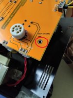
I'm worried, it's a Chinese creation. There are two more PCB ground connections - to turntable grounding and AC inlet ground (marked in the pictures).
I still don't know where the included nylon pads were used.


It is not usual for the signal ground to be connected to the case.
I'm worried, it's a Chinese creation. There are two more PCB ground connections - to turntable grounding and AC inlet ground (marked in the pictures).
I still don't know where the included nylon pads were used.
Completed the skunkie mods last night with a 750k resistor and quality mica caps. The difference is very significant and in my case has turned this little preamp into really something special.
There is a significant bass boost - I've completely removed my sub from my 2 channel setup). Mids are more forward (the way I like it) and highs more detailed and airy. I was about to start a 834 build, but no longer need to.
Even my wife, who isn't remotely interested in my system, stopped what she was doing and couldn't tear herself away.
So let me check - reducing the 750k resistor to 732k will increase or decrease the base? Going from 910 to 750 has produced a very significant increase - too much on some tracks.
I have owned the T11 for a number of years, and at first the hum drove me mad, but on opening up, found that none of the leads had been twisted. That dropped the hum considerably.
I performed the Skunkie Mods a couple of months ago, and it sounds fantastic, so thank you.
However, over the weekend, the Primary went open on the Mains Transformer. If anyone knows where I could source a replacement, I would be grateful - however, I'm wondering if it is a better idea to build a quality external PSU. I have a suitable enclosure lying around, it would eliminate hum, and I can address other weaknesses - not least use a 240v Primary rather than the 220v fitted. It doesn't look like a high quality transformer. If it wasn't for the 15v tap, I could get a quality transformer as an off the shelf part.
Mine is a custom built T10 with the toroidal transformer already in a separate enclosure. I had significant hum anyway. The only thing that stopped the hum was shuffling the tubes. I'm using 2 x Gold Lions and a Tung Sol (all 12AX7's). The GL in spot 3 was noisy. Putting the Tung Sol into spot 3 silenced the unit. Get a single 7025 tube, put it into position 3 and see what happens.
Douk have managed to supply a replacement transformer (cost $30 to UK). This has a 230v Primary which is a step in the right direction for UK mains.
However, I am going to still build an external PSU and see how much of a difference taking the magnetics out of the enclosure makes. I am probably going to build a 834p Clone at some point in the future, so will probably adapt it for that.
However, I am going to still build an external PSU and see how much of a difference taking the magnetics out of the enclosure makes. I am probably going to build a 834p Clone at some point in the future, so will probably adapt it for that.
- Home
- Amplifiers
- Tubes / Valves
- Mods to "Little Bear" phono-preamp