Back to the motor:
Of course you can transplant the element into an external motor can, I had thought about that too - lots of mass and a vibration-damping filler.
But this does not eliminate the cause.
The installed synchronous motor M303 is a 50Hz/300rpm 16VAC/2VA type. Directly operated via an 8VA small mains transformer, an 8.2µF series capacitor to the second winding ensures the start-up and the almost 90° phase relationship. This simply cannot work here. A simple calculation confirms the measurement, motor phase 2 is overvoltage by a factor of 1.355. The first emergency measure is a parallel resistor of 750 ohms to motor phase 2. The value of the capacitor can also be tweaked, but this arrangement does nothing to improve the handling of the EMF.
Two independent voltage sources are required, which can be manipulated both in terms of phase and amplitude. And this is the way I have chosen.
The frequency of the alternating voltage is fixed, 50Hz constant, the phase relationship is ideally 90°, but small mechanical deviations (manufacturing tolerances) could also lead to 89° or 91° - the aim is the lowest possible natural vibrations, perfect, rumble-free running.
As a time function, only a spectrally pure sine wave is suitable, that is clear to everyone. So I first dimensioned a 4th or 8th order active low-pass filter (I'd have to look it up!), a power supply unit and a suitable power amplifier. Everything per motor phase.
The self-made rotary/angle encoder was to tell my µC program the actual value of the control loop. Two independent PWMs represented the manipulated variables (in frequency, amplitude and phaseshift).
I'm working on the control program and the control loop in the lab.
At some point I gave up the PWM idea, because the accuracy was always a little dependent on which ATMEL µC I used.
The temporary solution (to this day) was a classic Wien bridge oscillator as the core, but here too I would have to research exactly how I could set the exact frequency (and thus the speed) and phase shift in detail in order to achieve the desired accuracy.
Ultimately, an elegant digital solution emerged - and it has been lying dormant in the box ready for use for several years:
Two DDS components and a stylish, slim program for almost any ATMEGA or ARDUINO. The core couldn't be realized more optimally. It works completely problem-free and just needs to finally be used, I don't have enough (free) time.
Good night,
HBt.
Two DDS components and a stylish, slim program for almost any ATMEGA or ARDUINO. The core couldn't be realized more optimally. It works completely problem-free and just needs to finally be used, I don't have enough (free) time.
Good night,
HBt.
Using 4 capacitors averages out variations, 4 1% caps in parallel gives a 0.5% capacitor. Also caps are usually available only in E3 and E6 values, not E12, so paralleling can be handy to get to particular values without committing to a rare brand of cap. 10nF and 100nF caps are always going to be the easiest and cheapest to source.Dear Mark,
the hidden question is not how can you still achieve the product of R times C equals 75µsec, but why does Cambridge Audio use four times 10nF capacitors?
Not sure about the point about Self's assertion as I have no idea which chapter of which book you refer to....
Green Book
Thank you Mark Tillotson,
sqrt(4) = 2
1 / 2 = 0.5
And you are now directly concluding - just as Douglas Self does in his green work - that four components with a tolerance of 1%, connected in parallel, should lead to a new component with 40nF 0.5%.
Well, that's not correct either.
"your lot would be to pick four components from a set of at least 76 - resulting in 1282975 possible combinations. A small computer randomization program shows (...)" [quote hbtaudio]
It is a lottery game!

It wouldn't be impossible to make a machine that takes a bandolier of through-hole caps and measures each one, printing its value on the cardboard strip and stepping/repeating for all of them automatically! Or cut and re-bin by value.
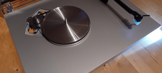
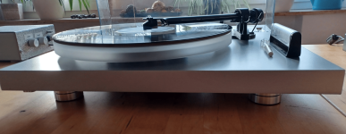
I've recently been playing around with the old Pro-Ject Audio Debut III esprit (an entry level turntable):
More mass!
More mass!
Attachments
-
 ALU_SUBTeller_1.png302.5 KB · Views: 78
 -
 ALU_SUBTeller_2.png309.6 KB · Views: 68
 -
 Fuß_u_Zarge.png172.5 KB · Views: 73
 -
 Füße.png237.4 KB · Views: 83
 -
 Höhendifferenzen_Kork_Gummi_Acryl_Basis_1.png289.5 KB · Views: 99
 -
 Höhendifferenzen_Kork_Gummi_Acryl_Basis_2.png288.2 KB · Views: 106
 -
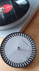 LagerAchse_und_Winkelgeber_.png264 KB · Views: 79
 -
 stylisch_Alu_Füsse_1.png302 KB · Views: 84
 -
 stylisch_Alu_Füsse_2.png242.6 KB · Views: 77
 -
 Subteller_aus_Plastik_original.png244.8 KB · Views: 85
The toy is still electrically powered by my analog Speedbox, a makeshift solution.
First things first, the sound has changed fundamentally - whether it's a psychological phenomenon, I don't know. But my first impression confirms the physics, namely F = m * a. The most delicate external vibration, let's say impulse, is transmitted to the tactile sensor, the MM cartridge. This was to be expected, but the previously disturbing groove noise (as if listened to with a stethoscope) is no longer pronounced - this disturbance has disappeared and the overall sound now has a completely different foundation, much better and seemingly more natural. However, this change really costs a lot of money, subplatters and feet add up to a lot, this upgrade is not cheap. I also have to come up with something for the inevitable decoupling from the floor, perhaps a bamboo board with the original rubber feet - or, if you do the math correctly, an analysis?!
The manufacturer states a total weight of 5100g (without a support mat), I have weighed the following components:
Acrylic platter
m1 = 897g
Cork-rubber mat
m2 = 130g
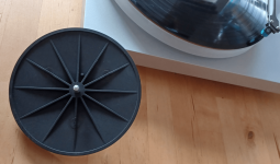
Plastic sub platter
m3 = 134g
4 pieces of plastic rubber damper feet
m4 = 56g (in total)
New total mass;
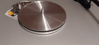
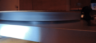
Aluminum sub platter
m3' = 695g
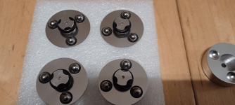
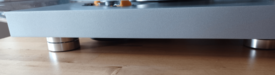
4 pieces of aluminum (with steel balls, multi-piece) feet
m4' = 288g (in total)
Total = 6023g.
First things first, the sound has changed fundamentally - whether it's a psychological phenomenon, I don't know. But my first impression confirms the physics, namely F = m * a. The most delicate external vibration, let's say impulse, is transmitted to the tactile sensor, the MM cartridge. This was to be expected, but the previously disturbing groove noise (as if listened to with a stethoscope) is no longer pronounced - this disturbance has disappeared and the overall sound now has a completely different foundation, much better and seemingly more natural. However, this change really costs a lot of money, subplatters and feet add up to a lot, this upgrade is not cheap. I also have to come up with something for the inevitable decoupling from the floor, perhaps a bamboo board with the original rubber feet - or, if you do the math correctly, an analysis?!
The manufacturer states a total weight of 5100g (without a support mat), I have weighed the following components:
Acrylic platter
m1 = 897g
Cork-rubber mat
m2 = 130g
Plastic sub platter
m3 = 134g
4 pieces of plastic rubber damper feet
m4 = 56g (in total)
New total mass;
Aluminum sub platter
m3' = 695g
4 pieces of aluminum (with steel balls, multi-piece) feet
m4' = 288g (in total)
Total = 6023g.
The turntable bearing
Pin, axle - diameter 6mm - length approx. 34mm, effective 19mm,
i.e. there is no more than 15mm left for the brass bushing, at the end of the tube is a tiny stainless steel ball (or is it a teflon mirror?).
The bushing is mounted in a strange plastic part ...
Strange - and this is supposed to be able to carry the weight of almost 2000g in the long term - CEO Heinz Lichtenegger is always coming up with something new.
#
I filled the huge cylinder bore at the bottom to accommodate the bearing yesterday with sand, these tiny garden pond stones, and sealed it. One less cavity ... more silence now.
The mount and holder of the steel ball (of the entire bearing) is really tiny, the visible steel disk on the surface desk is only cosmetic. At some point the plastic end will break.
As the next upgrade idea I would already know something "bear it", among other things with a ceramic ball and a can from the solid.
Last edited:
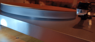
After a few days of listening, I'm completely amazed at what this "simple MDF board" can do. The smoothness and stability is astonishing -> why not like this right from the start?
Rumbling, synchronisation fluctuations and groove noise are now history - a better tonearm plus 2-phase synthesis electronics and "the board" would have grown up.
The only thing I can say about the 651P equaliser is, that its taste and function are now completely fine, without any faults.
In conclusion,
no matter which equaliser you use, an MM doesn't mutate into an MC - but as an entry-level combination, it's really not a bad choice.
However, I have repeatedly realised one thing:
today's LP releases are all rubbish, it pulls, it crackles ... old discs from the 1960s, 70s and 80s behave perfectly!
Bye,
HBt.
God job. My own Pro-ject had me chasing my tale when refurbishing my RIAA... Turned out most of the problems actually started at the the end of the pick-up, same problems as described here.
- Home
- Source & Line
- Analogue Source
- Modifications (drive and EQ)