What is going wrong with the cheap
Pro-Ject Debut III Esprit and Cambridge Audio 651P ?
Sorry,
the first post is to give me some air. I'll report on the drive modifications later, first my annoyance about the EQ.
First of all, I haven't listened to an MM system for decades, I prefer MCs. But in the context of the OREAD project and other gimmicks, I had announced to buy the cheapest MM system and so on, interested people can read the thread about it.
Now the AT-VM95C is mounted, adjusted, everything is fine so far. A test run is needed, ok - I have to add that I bought a CA 651P some time ago, more or less in passing. What for, for comparison, comparison with my own products. But what a disappointment, countless equalizers ... My God, with an MC you could get something out of the product, but with the current test formation ... No, it distorts, it's slightly muffled, zero atmosphere, but above all ADELE 19 distorts like the plague.
Well, no problem, I'll take it apart and get to the bottom of the problem. Why am I sure that the CA651P is rubbish? Because I dusted off my old PEARL - I've never listened to it directly, only with MC-Pre.
The original Pearl 1 doesn't distort, it rocks ... My iPEARL rocks and simply goes off like a rocket.
What is going on with Cambridge Audio (?), nothing is really usable from this company(!) - and I have several products from them.
Anyway,
here in this thread I will publicly disassemble, analyze and modify the EQ - so that it works without failing at the cheapest MM.
Attachments


I have that one too, as well as the DacMagic Plus upsampler - and it was great until its internal power supplies started getting into complete mischief ... In the meantime, the CD player has been acting up more often (it suddenly just stops playing the CD, sometimes it opens the drawer ...)
What can you say?
First of all, everything works (now) perfectly, but CA is a big bummer.
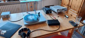
At the moment Carmel is rocking with her album the drum is everything, no audible and disturbing distortions on a record that is 40 years old - nothing cracks, nothing pulls. And it was this LP, or Carmel, that saved my life in the 1980s. It has to be said that the current products and record releases are without exception flawed junk, the quality of the record is subterranean. Not only the excessive loudness, the lack of dynamics, the clipping, the limitless compression, no, even the pressing is fundamentally flawed.
This has been my observation since I started listening to LPs again - and I listen to them because all digital recordings are also terribly compressed and mastered to maximum loudness - or am I wrong? Until the mid-1980s, tapes were perfectly fine, even CDs.
But after the (daily) hassle (with the disposable products), now a big compliment to Wayne Colburn and his Pearls:
My goodness, it's really addictive and simply a great pleasure to enjoy a simple MM, mounted on a strange tonearm tube, driven by the second worst drive I could think of, on the PEARL 1, running up to top form.
Thanks Wayne
for the inspiration to build and think through this little circuit.
🙂
First of all, everything works (now) perfectly, but CA is a big bummer.
At the moment Carmel is rocking with her album the drum is everything, no audible and disturbing distortions on a record that is 40 years old - nothing cracks, nothing pulls. And it was this LP, or Carmel, that saved my life in the 1980s. It has to be said that the current products and record releases are without exception flawed junk, the quality of the record is subterranean. Not only the excessive loudness, the lack of dynamics, the clipping, the limitless compression, no, even the pressing is fundamentally flawed.
This has been my observation since I started listening to LPs again - and I listen to them because all digital recordings are also terribly compressed and mastered to maximum loudness - or am I wrong? Until the mid-1980s, tapes were perfectly fine, even CDs.
But after the (daily) hassle (with the disposable products), now a big compliment to Wayne Colburn and his Pearls:
My goodness, it's really addictive and simply a great pleasure to enjoy a simple MM, mounted on a strange tonearm tube, driven by the second worst drive I could think of, on the PEARL 1, running up to top form.
Thanks Wayne
for the inspiration to build and think through this little circuit.
🙂
Attachments
A lot helps a lot (thought the CA product inventors)
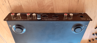
Photo album today ...
Photo album today ...
Attachments
A lot helps a lot (thought the CA product inventors)
Photo album yesterday ..!
Photo album yesterday ..!
Attachments
-
 der_Differenzverstärker_Modul_1.png741 KB · Views: 96
 -
 die_erste_Stufe_Modul_1.png705.4 KB · Views: 92
 -
 Draufsicht_EQ_und_PSU.png868.7 KB · Views: 106
 -
 Draufsicht_gesamt.png658.7 KB · Views: 96
 -
 EQ_und_TP2_als_Subsonic_Filter.png584.5 KB · Views: 83
 -
 freie_Sicht.png431.7 KB · Views: 95
 -
 Modul_1.png314.8 KB · Views: 95
 -
 Murks_1.png425 KB · Views: 88
 -
 ohne_470µ_und Haube.png790.3 KB · Views: 86
 -
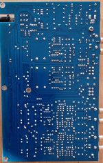 Platine_Lötseite_1.png809.2 KB · Views: 94
 -
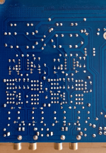 Platine_Lötseite_2_MC_MM_Eingang.png722.6 KB · Views: 78
 -
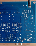 Platine_Lötseite_3_EQ_und_PSU.png599.6 KB · Views: 81
 -
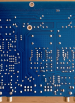 Platine_Lötseite_4_EQ_und_Subsonic_Filter.png651.9 KB · Views: 86
What is, or was, the causal problem?
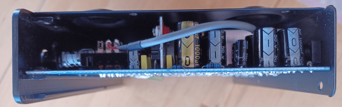
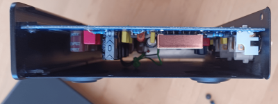
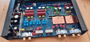
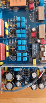
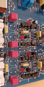
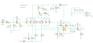
First of all, the capacitance of the signal line from the tonearm / headshell to the input of the EQ. 136pF determined by measurement, a look at the AT data sheet confirms the VM95C 100 to 200pF with 47kOhm as load. The assembly can therefore be carried out from this point of view, but the equalizer may now contribute a maximum additional load capacitance of 64pF. Unfortunately, the input capacitance of the 651P is 306pF statically and 210pF dynamically. In terms of measurement technology, this also corresponds exactly to the soldered-in blue 220pF monsters at the input of the first module, the first stage.
Gain_stage_1_MM: 26.4dB
Gain_stage_2_MC: 43.3dB
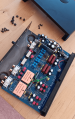
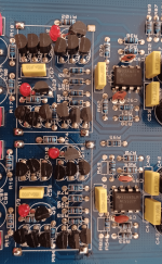
Both input amplifiers are actually completely identical and quite adventurously designed - so I would implement it differently, but never mind. With good will, I can understand the designers' thoughts, but no - that's not how it's done.
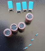
First you desolder the 220pF (63Vdc, 5% PP types) and second the 470µF bipolar 6.3Vdc coupling capacitor, with a small red WIMA FKP 10nF connected in parallel. Somehow this reminds me of the high-end scene 25 years ago, when blackgate plus 10nF was the biggest thing.
Now comes the biggest sticking point:
without the right tools and a corresponding workstation, you cannot replace a single component on the multilayer board (not without destruction, something always breaks). So' conventional manual work is not fun - these circuit boards are actually not repairable, they are all disposable lighters. It's not worth it.
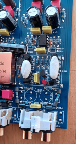
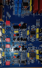
I replaced the entire input circuit with 68k - 22µF (100Vdc) || 10nF - parallel 150k; no parallel load capacity. Unfortunately, this also leads to a fairly large DC offset, which was already very high with the original 51kOhm base resistor, but is now between 7 and 10 volts. Without dimensioning the entire negative feedback network to have a higher resistance, an AC voltage coupling, a DC blocker, is required. 1mF/16Vdc solves the problem (and also creates a marginally new one).
The variant designed for MC has such an extremely low resistance that there is no need for a coupling capacitor at the input - 0.2mV does not cause any problems with any MC system, but as a precaution I added 27Ohm in the series. Here (as a first thought) you can do without both bipolar 6.3V (470µ and 220µ) coupling capacitors.
(2 times) 3 times 166.7µA IE, divided between six 2SA970GR, shot noise not reported! DC measurements ok; AC is still missing, as is the practical test and the disclosure of the circuit, if that is permitted - but it is definitely buzzing on the internet.
More on that later.
Good night,
HBt.
First of all, the capacitance of the signal line from the tonearm / headshell to the input of the EQ. 136pF determined by measurement, a look at the AT data sheet confirms the VM95C 100 to 200pF with 47kOhm as load. The assembly can therefore be carried out from this point of view, but the equalizer may now contribute a maximum additional load capacitance of 64pF. Unfortunately, the input capacitance of the 651P is 306pF statically and 210pF dynamically. In terms of measurement technology, this also corresponds exactly to the soldered-in blue 220pF monsters at the input of the first module, the first stage.
Gain_stage_1_MM: 26.4dB
Gain_stage_2_MC: 43.3dB
Both input amplifiers are actually completely identical and quite adventurously designed - so I would implement it differently, but never mind. With good will, I can understand the designers' thoughts, but no - that's not how it's done.
First you desolder the 220pF (63Vdc, 5% PP types) and second the 470µF bipolar 6.3Vdc coupling capacitor, with a small red WIMA FKP 10nF connected in parallel. Somehow this reminds me of the high-end scene 25 years ago, when blackgate plus 10nF was the biggest thing.
Now comes the biggest sticking point:
without the right tools and a corresponding workstation, you cannot replace a single component on the multilayer board (not without destruction, something always breaks). So' conventional manual work is not fun - these circuit boards are actually not repairable, they are all disposable lighters. It's not worth it.
I replaced the entire input circuit with 68k - 22µF (100Vdc) || 10nF - parallel 150k; no parallel load capacity. Unfortunately, this also leads to a fairly large DC offset, which was already very high with the original 51kOhm base resistor, but is now between 7 and 10 volts. Without dimensioning the entire negative feedback network to have a higher resistance, an AC voltage coupling, a DC blocker, is required. 1mF/16Vdc solves the problem (and also creates a marginally new one).
The variant designed for MC has such an extremely low resistance that there is no need for a coupling capacitor at the input - 0.2mV does not cause any problems with any MC system, but as a precaution I added 27Ohm in the series. Here (as a first thought) you can do without both bipolar 6.3V (470µ and 220µ) coupling capacitors.
(2 times) 3 times 166.7µA IE, divided between six 2SA970GR, shot noise not reported! DC measurements ok; AC is still missing, as is the practical test and the disclosure of the circuit, if that is permitted - but it is definitely buzzing on the internet.
More on that later.
Good night,
HBt.
Advertising does it
For some unknown reason, I don't particularly like CA - and not just because it's always the same old wine in new bottles. I'll simply attach the familiar schematic of the 640P, it's identical to the 651P, the only thing missing is the main switch - and the WIMA 10nF / 63Vdc FKPs or the other wonder capacitors simply turn a 640 into a 651, that's all. The circuit itself is, as usual with CA, the same stuff. Nothing' but advertising slang.
#
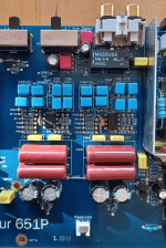
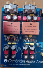
The red reference LEDs light up extremely brightly on my MC branch, while they glow downright dark on the MM branch. Do the chinese CAs use different types?
For some unknown reason, I don't particularly like CA - and not just because it's always the same old wine in new bottles. I'll simply attach the familiar schematic of the 640P, it's identical to the 651P, the only thing missing is the main switch - and the WIMA 10nF / 63Vdc FKPs or the other wonder capacitors simply turn a 640 into a 651, that's all. The circuit itself is, as usual with CA, the same stuff. Nothing' but advertising slang.
#
The red reference LEDs light up extremely brightly on my MC branch, while they glow downright dark on the MM branch. Do the chinese CAs use different types?
Attachments
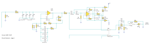


I think it would be better not to simply connect the BJTs in parallel, there should already be a selected pair formation. Perhaps an OP27 would also work well at this point, you would have to try it out.

75µsec (replaces R11, C8 & C9)
can be realized alternatively with four 10nF FKPs 1% - and poof, you have a CA 640P (and with a switch an 651P) CLONE, only slightly better than the original one.

And please' with a better PSU +/-12Vdc.
can be realized alternatively with four 10nF FKPs 1% - and poof, you have a CA 640P (and with a switch an 651P) CLONE, only slightly better than the original one.
And please' with a better PSU +/-12Vdc.
Continued story
First of all, the azur 651P equalizer works now flawlessly, but I still don't like the product. But all in all, it's perfectly fine - it now tugs noticeably less on my Adele 19 LP, which wouldn't really have gone through 1970s quality management anyway. The lump of vinyl would have been melted down again, and so on and so forth. The lowest budget ensemble is clearly noticeable, an entry-level MM cartridge with a conical stylus can't hide its physical weaknesses, an MC can handle Adele 19 better, for example. But with old LPs, the toy really comes into its own - a decent punch with clear highs. The azur 651P is also practically noise-free, and you will look in vain for hum interference or power supply ripples. The PEARL is naturally somewhat different. Long story short - I don't want to complain any further: the 220pF are quickly removed and while you're at it, you can also eliminate the huge DC offset of the first stage. C1 and C6 of the power supply can actually be doubled in value, which is normally done with this type of circuit. But it just doesn't fit into the housing. But the two integrated voltage regulators will fix it - and are already working at their limit. The sound and function are flawless. Whether you like it or not may also depend on the program material and the combination of tonearm and cartridge.
The PEARL is a smooth operator, but "keine Aphrodite".
Greetings and have fun,
HBt.
Or 1k + 1k5 into 10nF || 10nF || 10nF, exactly 75us with only E6 series.75µsec (replaces R11, C8 & C9)
can be realized alternatively with four 10nF FKPs 1% - and poof, you have a CA 640P (and with a switch an 651P) CLONE, only slightly better than the original one.
View attachment 1266381
And please' with a better PSU +/-12Vdc.
Detour to the drive
In its original condition, the two-phase synchronous motor rumbles and jerks, unfortunately it also transmits its 50Hz voltage like a radio transmitter. Both the vibrations and the electromagnetic interference in the pickup circuit are very disturbing in the original, i.e. unpacked, condition. But I assume that the problem is largely known. The Pro-Ject Audio Debut III Esprit is actually more of a pre-assembled kit than a full-size turntable. However, that doesn't matter, because not every young person can afford a full-sized REGA - and the CEO is so charismatic
🙂.
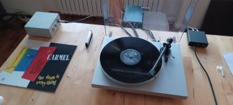
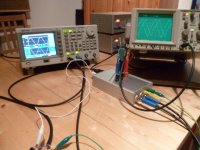
To get in the mood for the topic, I'm attaching a set of old photos.
In its original condition, the two-phase synchronous motor rumbles and jerks, unfortunately it also transmits its 50Hz voltage like a radio transmitter. Both the vibrations and the electromagnetic interference in the pickup circuit are very disturbing in the original, i.e. unpacked, condition. But I assume that the problem is largely known. The Pro-Ject Audio Debut III Esprit is actually more of a pre-assembled kit than a full-size turntable. However, that doesn't matter, because not every young person can afford a full-sized REGA - and the CEO is so charismatic
🙂.
To get in the mood for the topic, I'm attaching a set of old photos.
Attachments

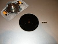


The 50Hz scattering problem can be solved quite easily, as can the rumbling problem -> you simply use a sensible DC motor. Why does it have to be a massively thick synchronous motor, a fat one at that too, with cogging moments and serious jerking?!
To avoid the radiation, I wrapped the motor in copper foil and coated everything with iron particles, a magnetic wall paint, and grounded it separately. The small plastic lids also suffered the same thing - also copper-plated and metallized with this great coating. Last but not least, new signal lines and everything well shielded.
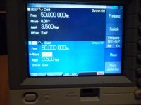
The actual drive disaster requires a more complex procedure to solve; a four-square operation is required. So sine and cosine, with minimal voltage so that the motor starts' a slightly different power supply is needed. More on that later.
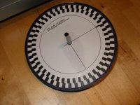
For fun, I upgraded the subplate to a rotary encoder.
To avoid the radiation, I wrapped the motor in copper foil and coated everything with iron particles, a magnetic wall paint, and grounded it separately. The small plastic lids also suffered the same thing - also copper-plated and metallized with this great coating. Last but not least, new signal lines and everything well shielded.
The actual drive disaster requires a more complex procedure to solve; a four-square operation is required. So sine and cosine, with minimal voltage so that the motor starts' a slightly different power supply is needed. More on that later.
For fun, I upgraded the subplate to a rotary encoder.
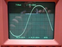
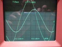
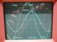
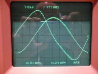
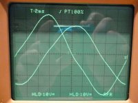
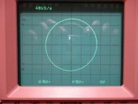
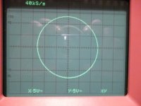
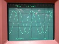
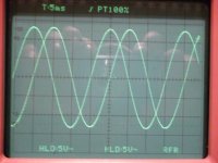
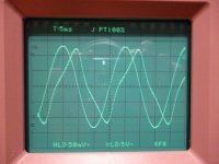
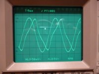
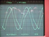
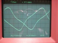
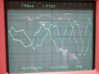
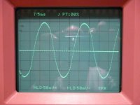
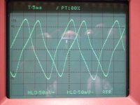
The oscilloscoped voltage curves of the motor windings in the original are shown in the pictures above.So are you going to put the motor on its own and leave those elastic bands?
I carried out a lot of small experiments to record the EMF of the individual phases, of course the currents, simply the entire program - to determine whether this motor could even be suitable as a driving element.
To be honest, you have to say that it is unsuitable for the Debut III. The whole concept is hollow - but acceptable to revitalize the entry-level market (1990 to 2010). Pluspoint, it stubbornly follows the network frequency - that's probably what the CEO was after.
I even tried out the Speedbox S at the time, and a friend later bought it from me. There's nothing to say against this little device, it leads to noticeable and audible improvements - that's no wonder, but one phase is not enough, among other things... but I don't want to go into this little gimmick in more detail.
Ultimately I decided on the motor and its own two-phase power supply.
Some more old pictures.
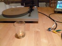
You can see the additional cork-rubber mat and the glass of whiskey. Unfortunately the tonearm height doesn't fit; the height of the simple arm is not adjustable. The easiest and quickest solution was the mat, at the expense of the small acrylic plate. Oh yes, the tonearm - is the next topic 😢
You can see the additional cork-rubber mat and the glass of whiskey. Unfortunately the tonearm height doesn't fit; the height of the simple arm is not adjustable. The easiest and quickest solution was the mat, at the expense of the small acrylic plate. Oh yes, the tonearm - is the next topic 😢
Attachments
-
 17_falsche Phasenlage.JPG112.8 KB · Views: 70
 -
 16_highend.JPG72.1 KB · Views: 82
 -
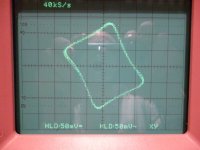 15_korrekte_Phasenlage_Ströme.JPG215.4 KB · Views: 80
 -
 14_88_Grad.JPG60.2 KB · Views: 75
 -
 13_92_Grad.JPG56.5 KB · Views: 75
 -
 12_U.JPG60.1 KB · Views: 73
 -
 11.JPG62.1 KB · Views: 66
 -
 10_I_und_U.JPG221.6 KB · Views: 75
 -
 9.JPG60.5 KB · Views: 72
 -
 8.JPG61.7 KB · Views: 82
 -
 7_strom_detail.JPG221.6 KB · Views: 80
 -
 6_strom_detail.JPG213.3 KB · Views: 75
 -
 5_emk.JPG231 KB · Views: 69
 -
 4.JPG98.5 KB · Views: 75
 -
 3.JPG65.9 KB · Views: 82
 -
 2.JPG79.5 KB · Views: 70
 -
 1.JPG106.2 KB · Views: 80
Last edited:
Dear Mark,Or 1k + 1k5 into 10nF || 10nF || 10nF, exactly 75us with only E6 series.
the hidden question is not how can you still achieve the product of R times C equals 75µsec, but why does Cambridge Audio use four times 10nF capacitors? And of course Self's assertion, see page 175 & 178 in the green paperback - It's not really correct and if it were, it's not exactly practical: your lot would be to pick four components from a set of at least 76 - resulting in 1282975 possible combinations. A small computer randomization program shows that Douglas Self got his idea wrong.
Regards,
HBt.
- Home
- Source & Line
- Analogue Source
- Modifications (drive and EQ)