There is no voltage divider before the tube stage , the full signal from the dac goes to the output stage , and what happens with that 100 times amplification factor of the 12AX7 tube? That's the point.
Did you replace the 68k resistor?
And yes the amplification factor is about 1x with is normal for this kind of tube stage, it is just a buffer.
Anode/cathode follower stage. Just do your math on the stages.
And yes the amplification factor is about 1x with is normal for this kind of tube stage, it is just a buffer.
Anode/cathode follower stage. Just do your math on the stages.
No I did not . I have cd88 , and you said in your post #10 that : "the 66/88 has other output tubes ( 12ax7 ) so you do not have to change the 68K resistors but only the 33K resistors to 27K."Did you replace the 68k resistor?
And yes the second tube is a buffer [cathode follower] but the first tube is not. It is GRD cathode that can do quite good amplification.
Last edited by a moderator:
Did you replace the 68k resistor?
And yes the amplification factor is about 1x with is normal for this kind of tube stage, it is just a buffer.
Anode/cathode follower stage. Just do your math on the stages.
What? It's not a buffer. It's common cathode stage followed by a cathode follower. It usually have gain about half of Mu of the triode used in it.
What? It's not a buffer. It's common cathode stage followed by a cathode follower. It usually have gain about half of Mu of the triode used in it.
So as I said before the first tube is a grd cathode[or common cathode] stage , and it is not a buffer but a gain stage. Then what happened with the amplification here? Negative feedback?
The second tube is of course cathode follower and it is a buffer , but it doesn't matter here.
I do not now the name of the first stage, but the tube stage is called a dc coupled cathode follower and it has a amplification factor about 1x.
Playing around with the resistors of the first stage can change the amplification factor.
Playing around with the resistors of the first stage can change the amplification factor.
Last edited:
All of this is the tube stage:I do not now the name of the first stage, but the tube stage is called a dc coupled cathode follower and it has a amplification factor about 1x.
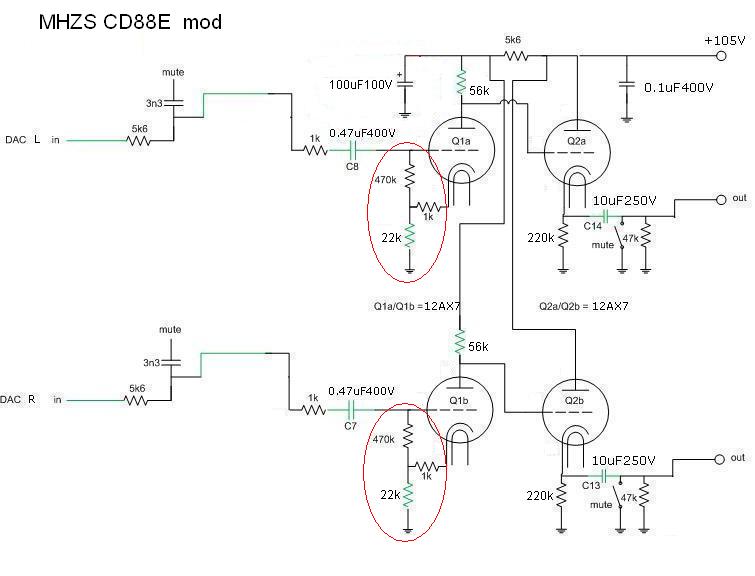
And it's not only a dc coupled cathode follower wchich has an amplification factor about 1x. Before cathode follower (Q2) there is a common cathode stage (Q1) wchich has much gain.
Playing around with the resistors of the first stage can change the amplification factor.
First of all as I said couple of postes before I did change 33k resistor and that did not make too much difference as far as amplification is concerned.
Second of all my point is : what happened to that 100 times amplification factor of the 12AX7 tube in the first stage. The amplification of the stage is not even 2 , it is actually probably less than 1.
So what part of the circuit is responsible for that. First , it is the very low anode supply voltage , but that's not enough to lower it[amplification] 100 times , so what else? My guess is that there must be some kind of negative feedback apllyed. I Suppose it is that part of the circuit I circled in red on the scheme. Let's concentrate on that. Remember 100 times factor , not a fraction of one percent
Attachments
I believe you will find that increasing the value of that 470K resistor to 1M or higher will bring the gain up quite substantially.
I believe you will find that increasing the value of that 470K resistor to 1M or higher will bring the gain up quite substantially.
Thank you for your contribution Stephen. That was my guess too , but before I do any changes I would like to learn some theory that stands behind that part of the circuit. What is the role it plays in that output stage. How it works. What might had been an idea of a designer if there was any.
It's part of a local neg feedback loop on that first stage. If you remove that 470k entirely, you would have basically the full gain of the tube, controlled only by the ratio of plate resistor / cathode resistors. The 1k is also part of that NFB, of course, and increasing it should also increase gain, but that will also drop current through the tube if you don't correspondingly shift the 22k. Personally, I would rewire the two stages into a single SRPP circuit, using 12AT7 or 12AU7 instead, which would no doubt require a voltage divider on it's input, due to very high gain, but should sound great tied direct to the output of the disgustingly-good-for-cheap PCM1742 dac.
It's part of a local neg feedback loop on that first stage. If you remove that 470k entirely, you would have basically the full gain of the tube, controlled only by the ratio of plate resistor / cathode resistors. The 1k is also part of that NFB, of course, and increasing it should also increase gain, but that will also drop current through the tube if you don't correspondingly shift the 22k. Personally, I would rewire the two stages into a single SRPP circuit, using 12AT7 or 12AU7 instead, which would no doubt require a voltage divider on it's input, due to very high gain, but should sound great tied direct to the output of the disgustingly-good-for-cheap PCM1742 dac.
Thank you Stephen again. You just confirmed what I have thought about that negative feedback part of circuit.
What I need now is to raise the gain of the first stage just 5-10% to get the output signal on the normal level. I understand that I can do that by increasing the value of that 470k resistor. That will lower negative feedback and at the same time will not affect the anode current. Have anybody tryed that before?
Regarding rewiring , there are also nice mods proposed by Thorsten and by my countryman as well , but I think I will not go thus far.
Last edited:
This is only to inform you that Thorsten has disagreed with opinion that there is negative feedback loop formed by 470k 1k and 22k resistors in the first stage.
Thorsten is hower banned from posting.
Thorsten is hower banned from posting.
Well, it could be viewed as positive feedback, but it certainly appears to me to be constraining the gain of the stage.
MHZS 33 Help Please
Hi, I know I am late to this discussion and the information is most likly barried in here, but I am going to ask.
I have a MHZS 33 and have replaced the tubes to 6H3N-E (based on a recomendation) and have used dynomat to dampen the chasis.
I would like to improve the sound from this unit if possible, but am working on a family of 6 budget.
1) I am currently using the coax out and Not the RCA, it looks like most are using RCA - Do these mods effect the coax digital out or after doing them would i want to switch over to the RCA out?
2) Should I do the mods orgionally posted by Koifarm post #1? and is this the best bang for the buck for the 33 ?
I am not an electriction, but I am good with replacing components and have the correct equipment.
Any and all basic straight forward information would trully be appreciated.
Thank you very much!!!!!!
Hi
After a while I'd like to call your attention back to the problem that has not been solved yet. The cracking noise heard in the backgroung when very low level signals are played.
Let us do the test. Try to play last 30 seconds of Phil Collins' Face Value record with raised volume and say what you hear in the background. Can you hear any loud cracking noise or not.
How to get rid of it?
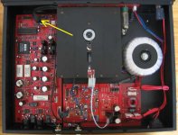
Geekey, another source of interference can be the flatcable of the displayboard. i use a ferritclamp on the flatcable to solve this.
Do you mean this flatcable?Geekey, another source of interference can be the flatcable of the displayboard. i use a ferritclamp on the flatcable to solve this.
Attachments
Geekey, another source of interference can be the flatcable of the displayboard. i use a ferritclamp on the flatcable to solve this.
Ferritclamp on the flatcable did not solve the problem in my case. Nothing has changed regarding the noise.
- Home
- Source & Line
- Digital Source
- Modification of MHZS CD players