The problem with 1612 is its output phase starts to shift sharply under 1KHz. This makes the mid bass a bit dry and thin.
On paper, looks like LME49720 is a good replacement. The THD is still very low and the phase shift keeps flat in the audio band. MUSES OP output phase runs up a bit in the HF area, still not too bad. Teac uses MUSES in their UD players which are AKM based. Probably MUSES and AKM are a good match? It's worth of a try.
Output phase in open loop gain or closed loop gain ? I doubt that the phase in closed loop gain is different than linear below 1khz.
The best candidate to replace the OPA1612 is OPA1642 in my opinion. It has a smaller band(which is better) and FET input, perfect for differential input(very high impedance). THD and IMD again very small. The output phase in the open loop gain is's very linear in the audio band and beyound. And let's not forget about the very good price 🙂
I've got an opa1642 laying around somewhere. If I find it. I'll give it a try.
Last edited:
Khadas incoming in three days. Exchanged Muses01 and 02 order for a dual 03. And couldn't find my 1642 so ordered 20 new ones. Also maybe to replace the 2x7 TL027 in my active speakers. Once i start modding those I'll make a new thread. I'll need a lot of help with those since I'm practically an idiot.
What is interesting for this thread is how the minimalistic Khadas compares to the modified and unmodified DX3 Pro. Can't wait to compare and share.
Since I was doing all round upgrades anyway I also decided to make myself new signal cables and interconnects with some Gotham 10561 GAC2 cables. 6 meter of cable for 2 pairs of 50cm interconnects and 1 pair of 2m signal cable to the active speakers (about €125 in material cost). Curious how the Gotham will compare to my QED custom (subwoofer line) cables.
Output phase in open loop gain or closed loop gain ? I doubt that the phase in closed loop gain is different than linear below 1khz.
The best candidate to replace the OPA1612 is OPA1642 in my opinion. It has a smaller band(which is better) and FET input, perfect for differential input(very high impedance). THD and IMD again very small. The output phase in the open loop gain is's very linear in the audio band and beyound. And let's not forget about the very good price 🙂
At very LF, feedback does not work that well. For an 100Hz signal, the cycle time is 10ms. A 90 degree phase difference is 2.5ms. This is a big time gap, the OP will keep chasing the input signal and the residual error after correction will sound pretty bad.
OPA1642 is a good choice. It's just the THD is higher, and the gain bandwidth is lower. For DSD, 4493 will have an internal LPF kick in so the OPA1642 will serve as the second stage LPF. Yet for 768K PCM, there will be HF noise around 49MHz which is too high for 1642. Another thing is JFET has higher input noise. On paper LME49720 is a better compromise. Sure, 1642 may sound warmer, and it will make immediate difference after swapping out the 1612.
@finnybear,
Had a very different experience with opamps myself. I decided to find out why opamps sounded as different from one another as they did in my dac output stage. Didn't seem like it should be that way, and of course I am very skeptical of novel theories blaming feedback. What I found out was the reason opamps didn't sound as good as they really should had to do with the power supply. That was even though the power supply was a well regulated, low noise, well filtered design. What fixed it was about 100uf of mixed size film caps soldered in parallel and connected from each of the +-15v rails to ground. No more blaming of opamp feedback would be needed, IME. Great sound now with OPA1612. There is more that could be said about it, but already posted in another thread: https://www.diyaudio.com/forums/digital-line-level/314935-es9038q2m-board-380.html#post5690955
Had a very different experience with opamps myself. I decided to find out why opamps sounded as different from one another as they did in my dac output stage. Didn't seem like it should be that way, and of course I am very skeptical of novel theories blaming feedback. What I found out was the reason opamps didn't sound as good as they really should had to do with the power supply. That was even though the power supply was a well regulated, low noise, well filtered design. What fixed it was about 100uf of mixed size film caps soldered in parallel and connected from each of the +-15v rails to ground. No more blaming of opamp feedback would be needed, IME. Great sound now with OPA1612. There is more that could be said about it, but already posted in another thread: https://www.diyaudio.com/forums/digital-line-level/314935-es9038q2m-board-380.html#post5690955
No, the feedback is not the problem. It's the phase performance of OP and is something a lot of people are not aware of.
Good power supply is the foundation. Different OPs may need specific treatments, etc. After the power supply is done correctly, you will start to see other problems pop up.
Talk about power supply, the min power supply for 1612 is about 4.5V. Even when TI claims 1612 can do rail-to-rail, still, the power supply voltage in DX3 is a bit low.
At very LF, feedback does not work that well. For an 100Hz signal, the cycle time is 10ms. A 90 degree phase difference is 2.5ms. This is a big time gap, the OP will keep chasing the input signal and the residual error after correction will sound pretty bad.
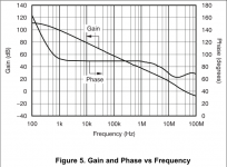
The phase is only 90degrees in the open loop condition - see the attached plot. All opamps have such a phase shift in the open loop condition, they only vary in the frequency. Its guaranteed by them being dominant-pole compensated. Closed loop there is no such phase shift apparent.
So what was it which made OPA1612 such a poor choice?
Attachments
At very LF, feedback does not work that well. For an 100Hz signal, the cycle time is 10ms. A 90 degree phase difference is 2.5ms. This is a big time gap, the OP will keep chasing the input signal and the residual error after correction will sound pretty bad.
OPA1642 is a good choice. It's just the THD is higher, and the gain bandwidth is lower. For DSD, 4493 will have an internal LPF kick in so the OPA1642 will serve as the second stage LPF. Yet for 768K PCM, there will be HF noise around 49MHz which is too high for 1642. Another thing is JFET has higher input noise. On paper LME49720 is a better compromise. Sure, 1642 may sound warmer, and it will make immediate difference after swapping out the 1612.
The "chasing your tail" stuff again? This phase shift would be easily measurable if it occurred in closed loop conditions.
OPA1612 is one of the top choices for this position, in my opinion. LME49720 is good too but some have popcorn noise and I had seen some measurements that indicated they had higher EMI susceptability than other similar op-amps (can't find references anymore, though). ADA4898-2 is worth a try as well but I don't think it will measure quite as well as the OPA1612 in terms of distortion.
Does anyone know the output impedance of the AK449x? If it's high enough then OPA828 might do the job, though it's a single only.
Last edited:
The phase is only 90degrees in the open loop condition - see the attached plot. All opamps have such a phase shift in the open loop condition, they only vary in the frequency. Its guaranteed by them being dominant-pole compensated. Closed loop there is no such phase shift apparent.
So what was it which made OPA1612 such a poor choice?
It is not the degree of phase shift, it is the delay time of the output which matters. At 100Hz, 1612's output is 2.5ms late when compared at, say 1KHz. This means the feedback is slow to react at 100Hz hence the correction errors will have bad effect on sound. One solution is to put phase compensation on the feedback loop yet there's nothing this sophisticated in DX3.
High speed OPs tend to have phase bump at LF. 1612 is unique that the phase can divert this much. It is interesting TI would market OPA1612 as an audio OP. Probably they think human ears are not sensitive to the phase difference at LF. However, it is the correction errors at LF which has impact on sound.
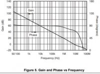
Look at how flat OPA1642 and LME49720 are at audio band:
Attachments
The "chasing your tail" stuff again? This phase shift would be easily measurable if it occurred in closed loop conditions.
OPA1612 is one of the top choices for this position, in my opinion. LME49720 is good too but some have popcorn noise and I had seen some measurements that indicated they had higher EMI susceptability than other similar op-amps (can't find references anymore, though). ADA4898-2 is worth a try as well but I don't think it will measure quite as well as the OPA1612 in terms of distortion.
Does anyone know the output impedance of the AK449x? If it's high enough then OPA828 might do the job, though it's a single only.
AK4493 has differential switched capacitor filter at the output. Basically it is a differential output OP. I will not be too worried about its output impedance except that I want to keep the output current low.
A phase shift isn't the same thing as a time delay. If there were really a mechanism for a 2.5mS delay inside the opamp then it would affect all frequencies equally, and we'd see that on the plot as a line continuing to slope downwards (with wrap-arounds) - ever higher phase shifts at higher frequencies. But we do not see that, we see the line going flat in the mid-band, at 90degrees and sticking there. Hence it cannot be a time delay that gives rise to the phase shift.It is not the degree of phase shift, it is the delay time of the output which matters. At 100Hz, 1612's output is 2.5ms late when compared at, say 1KHz.
They're stuck at 90degrees throughout the audio band - but if your theory about time delay was correct, the 90degrees phase shift they show at 100Hz means they too must contain a delay of 2.5mS. So what gives?Look at how flat OPA1642 and LME49720 are at audio band:
Exactly. A delay of 2.5ms is not physically possible. There is no mechanism to store information for 2.5ms.
phase shift is delay. It is just a different way to describe things. A positive 90 degree phase shift means there's a 90 degree delay between input and output sine waves.A phase shift isn't the same thing as a time delay. If there were really a mechanism for a 2.5mS delay inside the opamp then it would affect all frequencies equally, and we'd see that on the plot as a line continuing to slope downwards (with wrap-arounds) - ever higher phase shifts at higher frequencies. But we do not see that, we see the line going flat in the mid-band, at 90degrees and sticking there. Hence it cannot be a time delay that gives rise to the phase shift.
They're stuck at 90degrees throughout the audio band - but if your theory about time delay was correct, the 90degrees phase shift they show at 100Hz means they too must contain a delay of 2.5mS. So what gives?
Any circuit has delays. For analog circuits, often the delay/phase shift will vary among different frequencies. If the circuit has a consistent 90 degree shift from 20hz to 20kHz then usually this will not be a problem; however, if the circuit has a 180 degree shift below 1KHz then consistent 100 dergee from 1KHz to 20KHz, definitely I will have to check this LF band.
Exactly. A delay of 2.5ms is not physically possible. There is no mechanism to store information for 2.5ms.
You can easily create a 2.5ms delay with an RC circuit.
You can easily create a 2.5ms delay with an RC circuit.
You can take 2.5ms to charge up a capacitor to some voltage starting with DC, but it never charges up fully since it settles asymptotically. There is no sudden stop at 2.5ms. Have you even tried to delay audio by 2.5ms with an RC circuit?
Last edited:
You can take 2.5ms to charge up a capacitor with DC. Have you even tried to delay audio by 2.5ms with an RC circuit?
I meant you could design a circuit with the needed RC time constant.
Anyway, I am just here to explain to other DX3 owners why it is a bit thin on mid-bass. Other than the power supply fix, OP swap is the next step. 1612 will sound superb with the right design yet it is not the case for DX3.
I meant you could design a circuit with the needed RC time constant.
Anyway, I am just here to explain to other DX3 owners why it is a bit thin on mid-bass. Other than the power supply fix, OP swap is the next step. 1612 will sound superb with the right design yet it is not the case for DX3.
Except your explanation is not correct. If the op-amp is stable...
Can you demonstrate closed loop phase shift in the audio band with an OPA1612 due to its open-loop response? This should be quite measurable.
Other than the power supply fix, OP swap is the next step. 1612 will sound superb with the right design yet it is not the case for DX3.
Okay, that much we could probably agree on. 🙂
Don't know that the other guys are going to let you off about the delay though. Its a problem from an EE perspective, and potentially misleading for new guys who don't know much yet. The concern is mostly for them.
Last edited:
phase shift is delay. It is just a different way to describe things. A positive 90 degree phase shift means there's a 90 degree delay between input and output sine waves.
If phase shift really were delay, how to account for a phase advance of 90 degrees? A negative delay - meaning a circuit that predicts the future, producing an output before there's any input?
- Home
- Source & Line
- Digital Line Level
- [Modding] Topping DX3 Pro