Seems a lot of additional chips are needed for full digital? The I2S output from pcm2706 is bad or worse than spdiff output?
How does the Popu name inputs ? By number ?
No, by some funky use of the 7 segments to show the first two letters 'US' for USB, 'CO' for coaxial and 'AU' for analog (aux?).
Thanks, difficult to implement "USB 2" in that case. It is only optical so not very important. A better high res USB board can be added but is it really worth it ?
In hindsight I think this device has too many drawbacks. USB implementation is plain mediocre with PCM2706 and not high res (in 2016!). Only SPDIF is high res. When one has to buy a better 100$ USB board IMO the fun is gone. Regs are not very good ones, funky display, need to modify power amp, LM2596 creating nice spikes....
Lets send an email to the company and wait for the 2017 model 😀
The STA333BW board probably is more value for money.
Last edited:
In hindsight I think this device has too many drawbacks. USB implementation is plain mediocre with PCM2706 and not high res (in 2016!). Only SPDIF is high res.
Did you read the D2-41051 datasheet carefully? Its got ASRCs on the inputs and converts all input rates from 16kHz to 192kHz to 48kHz for internal processing (page 13). So high res is rather pointless.
Save
Then the device is rather pointless 😉
Had already seen that, it is contrary what other companies choose (96 kHz). I will skip it for sure. Anyway, it is 24 bit internally so the 16 bit USB implementation still is poor compared to what the device can achieve regardless how you look at it. It just screams for a better front end.
Had already seen that, it is contrary what other companies choose (96 kHz). I will skip it for sure. Anyway, it is 24 bit internally so the 16 bit USB implementation still is poor compared to what the device can achieve regardless how you look at it. It just screams for a better front end.
Last edited:
It just screams for a better front end.
This is DIY Audio, where there's a will there's a way!
For the STA333BW board I'm convinced that it is possible to hook in an 12S source to the inputs of the STA chip; run it at 96/88KHz and you avoid the STA doing any up or down sampling. Here's a cheap option to try initially;
384kHz Asynchronous USB to I2S/SPDIF CM6631A PCB - DIYINHK
I'm not sure if there will be any benefits of using isolated I2S inputs given the nature of the amp board - any thoughts?
This is DIY Audio, where there's a will there's a way!
🙂 I am the last to deny that but after some time and many experiments wisdom creeps in.
If costs are high to mod a device to what it should be ... and the total price equals/exceeds that of another better device maybe it is easier to buy the better device .....
48 kHz internally is quite limiting IMO. Also 16 bit USB is quite limiting, throwing 24 bit 96 kHz via SPDIF to it to have it resampled to 48 kHz. Ouch. I have bought many devices that appeared to have some severe limitations after I bought them. Maybe it is wiser not te be an early adopter 😉
* Waiting for parts for the STA board. No comment yet.
Scanning the market for an FDA with 2 x Toslink, 1 or 2 x SPDIF and high res USB. Anyone ?
Last edited:
🙂 I am the last to deny that but after some time and many experiments wisdom creeps in.
Just teasing Jean-Paul. We have a saying that you can't make a silk purse from a pig's ear...🙂
48 kHz internally is quite limiting IMO.
STA333BW operates at 96/88KHz 16/24bit internally but might possibly need a register setting for 24bit - need to read the datasheet carefully if I get to using a better source input.
Ray
Last edited:
I think it should sound similar to your D802 which uses the sta326.
BTW, I kill the sta326 in D802 while trying to measure it, so I ordered the Popu D2P to see how it sounds. I also order the sta326 chip to see if I can repair it.
How did this happen. I just killed a sta326 based amp by just playing it a bit loud(ish). Is this a sensitive chip?
What voltage was it fed?
//
"Trying to measure it"..... so shorting 2 pins when powered on....
Not many chips survive that 😉
Not many chips survive that 😉
If only it were that simple!😀
Thanks for the pointer (and the link in your follow on post).
What are you using as your supply currently, I get the capacitor bank aspect but are you still using a SMPS brick or have you gone for a ground up power supply? Just trying to tap into what you've learned so far.
To my simple thinking a shunt supply would seem like a good option, though I'm not aware of any designs with sufficient current for a loudspeaker solution. I do have a Twisted Pear Placid HD (which will deliver upto around 800mA I believe) that I could perhaps try for headphone operation?
Ray
I found that power supply makes a big difference. My experience here: http://www.diyaudio.com/forums/clas...d802-optimisation-tpa3116-11.html#post4530915
(scroll up the thread for more explanation!)
Cheers,
Mike
For the STA333BW board I'm convinced that it is possible to hook in an 12S source to the inputs of the STA chip; run it at 96/88KHz and you avoid the STA doing any up or down sampling.
Yes, that seems like the best way forward with that chip. An ARM Cortex M0/3/4 will almost certainly do the job of upsampling from RBCD. It'll make an excellent DAC and headphone DAC-amp but I fear its not for delivering the highest quality as a speaker poweramp due to its 21V supply limitation.
The higher the voltage the lower the current for the same output power. Its the current which sags the PSU. Of course I'm assuming output transformers here.
The higher the voltage the lower the current for the same output power. Its the current which sags the PSU. Of course I'm assuming output transformers here.
But for power supply lower voltage also means higher current. So I think it depends on power supply quality.
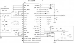
The sta333 board power supply rail doesn't have much decoupling near the chip. There a a 470uf rubycon (low grade) at input which is split into 2 left/right rails at the bottom of board into the chip with 2 0603 smd caps for each side (probably 100nf + 1uF based on the sta333 datasheet)
I put additional smd 10uf at the 2 rails by scraping away the paint exposing the copper.
For the sta333 board, I like to raise few points for discussion:
1. Increase decoupling for the VSS and VDD, currently there is 100nf for each
2. In the datasheet, section 8.2, "concerning component values, ....the less the lock time the higher the PPL output jitter. "
Can those PLL values be modded (like one of the known tweak for cs8412 receiver), currently uses 2k2 + 4.7nf // 680nf.
Slower locked time but better jitter?
3. Direct I2S into the pins 27~30.
I already have USB to I2S board so I can try it later. I can tap those pins from the bottom of the board (which is easier than from top)
Attachments
For the sta333 board, I like to raise few points for discussion:
1. Increase decoupling for the VSS and VDD, currently there is 100nf for each
Noticed this too, at the bottom of the PCB 1210 caps 10 µF 50V can easily be added. Or even larger tantalum caps. I only have 47 µF 35V AVX TPS left and maybe I will try them. While the board design is not the worst the designer skipped the datasheet recommendations.
Slower locked time but better jitter?
Yes, this is true for a PLL. By all means try it. It means that you will have to wait a second or 2 before it plays after power on / connection of digital source. Also, it may cause drop outs if it unlocks while playing due to too big incoming "speed" variations. Not likely however if source is stable. This will be audible.
//
Noticed this too, at the bottom of the PCB 1210 caps 10 µF 50V can easily be added. Or even larger tantalum caps. I only have 47 µF 35V AVX TPS left and maybe I will try them. While the board design is not the worst the designer skipped the datasheet recommendations.
On the contrary, I found the sta333 matches quite closely with the datasheet circuit. Even the layout is fairly ok compare to other boards I have. But the use of 0603 smd size is really hard to mod.
BTW, I have found the 3.3V regulator. Its the smd 3 pin regulator (U2) next to the mute button which takes 5V from 78m05.
The 3 pin smd regulator has marking "662", anyone know what it is?
Not on the contrary! As said, the designer made a nice design but forgot to include a 100 µF bulk cap and a few 1 µF caps....
I already noticed the reg as there is no other semiconductor to regulate 3.3V.
* "662" is Torex XC6206 3.3V 200 mA 0.25V dropout LDO reg.... Not even noise specs in datasheet. Uh oh 🙂
I already noticed the reg as there is no other semiconductor to regulate 3.3V.
* "662" is Torex XC6206 3.3V 200 mA 0.25V dropout LDO reg.... Not even noise specs in datasheet. Uh oh 🙂
Last edited:
- Home
- Amplifiers
- Class D
- Modding Taobao digital amps