When Deon builds this, I am sure we will get some measurements. I do not build stuff this big.
Here is the polar for 30 Hz, 500 Hz, and 1kHz. That is the other advantage of the Karlson aperture - it makes an acoustic lens that provides wide directivity - about 100 deg in this case up to 1 kHz.
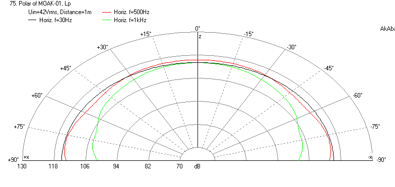
Here is the polar for 30 Hz, 500 Hz, and 1kHz. That is the other advantage of the Karlson aperture - it makes an acoustic lens that provides wide directivity - about 100 deg in this case up to 1 kHz.
Attachments
It will be a while before I can build this (financial issues the main reason), but there is two things that does concern me:
1. The subs that I build will have to stand right up against the wall. There is no other option in the space I have for them. Will the Karlsonators work in this kind of placement scenario?
2. The subs will be standing either side of a desk. This is again not something I have any control over as it is the only space I have for them. The main speakers will also be flanking the desk, but I can pull them forward so that they sit slightly in front of the desk's edges. My problem is that with the Karlsonator the woofers will be sitting close to the floor, and therefore be shaded by the desk. That is one of the reasons I thought of maybe going for the full TH/Karlson solution with the opening at the bottom- this will lift the woofers high enough so that they are not sitting below the top of the desk.
I am exited to build these, but I want to make sure that they will work in the space I have for them. As it stands, those are the limitations I have to live with for now, so any advice here will be appreciated.
Deon
Deon,
Here is the sim with the sub placed against a wall with a 48 dB Butterworth high pass filter at 200 Hz. You can see the result is still good, just sloping towards the deep bass end - nothing that some EQ'ing can't help. It will reduce the ultimate SPL to about 112 dB (flat) but that should be loud enough for your application as it looks like it will be in a room where you will get modes and room gain. Being next to the desk isn't a problem as the bass below 100 Hz is non directional. I think these will be quite an audio and cabinet statement as they are huge. I guess WAF is not going to be an issue? 🙂

Here is the sim with the sub placed against a wall with a 48 dB Butterworth high pass filter at 200 Hz. You can see the result is still good, just sloping towards the deep bass end - nothing that some EQ'ing can't help. It will reduce the ultimate SPL to about 112 dB (flat) but that should be loud enough for your application as it looks like it will be in a room where you will get modes and room gain. Being next to the desk isn't a problem as the bass below 100 Hz is non directional. I think these will be quite an audio and cabinet statement as they are huge. I guess WAF is not going to be an issue? 🙂
Attachments
Thanks, I will take a closer look at that thread.
Well, I had a closer look. Nothing in that thread convinces me that the Karlson aperture is a viable design element. There's a few sims, and quite a few pictures, but nothing demonstrating the actual viability of a Karlson-based alignment, e.g. actual impedance and FR comparison between a sim and a built system based on that sim (or a built system and its subsequent simulation).
For an idea of what I'm looking for, see The Subwoofer DIY Page v1.1 - Projects : "Proof of Concept #3"
It may be in another thread where I modeled a k15 with the same driver spec that Freddi made a measurement of freq response and impedance. The impedance peaks matched and the location of the characteristic "W" dip matched. Not everything will be perfect but the prediction of the bass knee is usually spot on and the suitability of the driver I producing a reasonable response without too much peakyness or sag is also useful. There is a lot of info and it has been tough to get comparisons as not too many people have measurements of a K15 or Karlsonator.
Originally Posted by xrk971
48 dB Butterworth high pass filter at 200 Hz
Originally Posted by Brian Steele The Subwoofer DIY Page v1.1 - Projects : "Proof of Concept #3"
a steep high-pass filter needs to be used to address the out of band noise
I think you both meant to say, Low Pass Filter 😉
@ Brian Steele
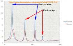
Interesting to see how the POC #3 sim compares to the design. I expect that David McBean might be interested in the impedance curve of the built system !
I observed these, but not sure what to make of them ?
Attachments
I think you both meant to say, Low Pass Filter 😉
Good catch. I've corrected the page.
I observed these, but not sure what to make of them ?
Yes, the slight upshift in the lowest impedance peak is interesting. I've noticed it in my earlier POC build as well. I didn't worry too much about it as it's well below the TH's passband. I thought at that time it might have something to do with my use of a segmented TH design. In this case however the expansion in the built TH is as close as I could get it to the sim. Maybe it's a result of the additional "volume" in each bend, though I would expect that to push the peak lower, not higher. Of course the only way to find out if it is bend-related is to build a TH without any bends at all, which I think is impossible 🙂.
@ Brian Steele
It's not the size of the peaks i was referring to, rather the shift sideways !
Yup, that's what I was referring to as well (upshift in frequency, not amplitude). It's most noticeable with the lowest peak.
The amplitude difference is most likely due to the effect of losses.
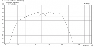
Non-flat because you see ripples and dips and peaks that are +/- 3dB - a very good performer for many speakers and especially given the broad bandwidth. Here is what this speaker can do in a wide band application with the addition of a 6 ohm + 10 mH BSC circuit (or EQ'ing):
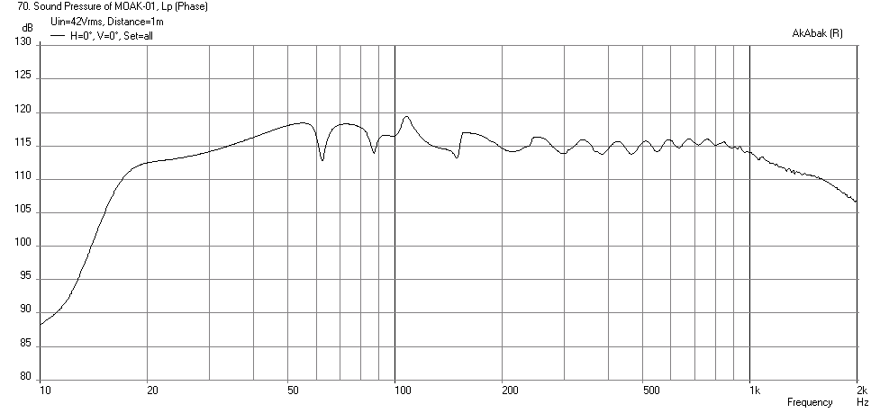
Can you find another speaker with high SPL capability that has -3dB point of 18 Hz on the low end and goes up to 1.16 kHz on the high end? That is 6 octaves!
Add a horn loaded CD tweeter and you have a nice 2-way that can rock the house (or stadium).
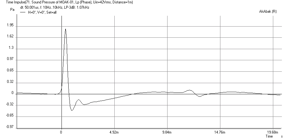
And here is the corresponding Impulse Response for this setup:
wow that a fine looking response. What driver is that? my brother has a pair of JBL 2226H (8 ohm) drivers would they be similar to these in a Karlson? Thanks and best regards Moray James.
PS: he also has a pair of EV DH1A happy doen to 500Hz or lower so yes a fine looking two way.
Last edited:
Moray James,
Thanks for the kind words! The simulations used an AE TD15H driver 8 ohms x 2 in parallel. A 10 mH and 6 ohm BSC was used to flatten the response in the upper range to match the bass. The specs are in post 1 by the OP. This driver has a generous 14 mm xmax and 94 dB efficiency. The specs say it is good to 2kHz so I expect cone breakup is probably just above 1.5 kHz?
Thanks for the kind words! The simulations used an AE TD15H driver 8 ohms x 2 in parallel. A 10 mH and 6 ohm BSC was used to flatten the response in the upper range to match the bass. The specs are in post 1 by the OP. This driver has a generous 14 mm xmax and 94 dB efficiency. The specs say it is good to 2kHz so I expect cone breakup is probably just above 1.5 kHz?
Hi xrk971
Thanks for the fantastic work so far. I have had another idea that I also want to throw in the mix.
I am going to build the MOAK, with dimensions of 2.5x the height, but the width cannot exceed 1.4x the standard width. Seeing as the depth remains unchanged, and that where the MOAK is going to stand, it needs to be at least 550mm deep- the one will stand next to a wall that is shaped like this:
So, I was thinking, the standard Karlsonator box is 450mm deep. For the MOAK, we increased the height and width, but not the depth. So why not make the box 550mm deep, and then fill the last 100mm (minus the thickness of the rear baffle) with damping material. This is a sketch of my idea:
That way the box won't 'see' the rear wall that much, which should have good benefits in depth and tightness of the bass. Then I remembered a design idea I read about that was meant to smooth out the response of the Jensen Transflex. It looks like this:
Could this work with the MOAK? What would the effect be? It would be simple just to make an opening in the bottom of the rear baffle between the MOAK and the damped chamber to achieve the same effect, like this:
I am curious to know what you think of these ideas.
Thanks,
Deon
Thanks for the fantastic work so far. I have had another idea that I also want to throw in the mix.
I am going to build the MOAK, with dimensions of 2.5x the height, but the width cannot exceed 1.4x the standard width. Seeing as the depth remains unchanged, and that where the MOAK is going to stand, it needs to be at least 550mm deep- the one will stand next to a wall that is shaped like this:
An externally hosted image should be here but it was not working when we last tested it.
So, I was thinking, the standard Karlsonator box is 450mm deep. For the MOAK, we increased the height and width, but not the depth. So why not make the box 550mm deep, and then fill the last 100mm (minus the thickness of the rear baffle) with damping material. This is a sketch of my idea:
An externally hosted image should be here but it was not working when we last tested it.
That way the box won't 'see' the rear wall that much, which should have good benefits in depth and tightness of the bass. Then I remembered a design idea I read about that was meant to smooth out the response of the Jensen Transflex. It looks like this:
An externally hosted image should be here but it was not working when we last tested it.
Could this work with the MOAK? What would the effect be? It would be simple just to make an opening in the bottom of the rear baffle between the MOAK and the damped chamber to achieve the same effect, like this:
An externally hosted image should be here but it was not working when we last tested it.
I am curious to know what you think of these ideas.
Thanks,
Deon
Deon,
I forgot to mention that the usual scaling if the height also applies to the depth, so it is 0.95m deep. I hope that is not too deep for you. Changing the width to 1.4x can actually be accommodated with equivalent change in depth to preserve volume. I have a question for you - how are you able to have such a large speaker indoors?
You don't have all the extra space for your damped section in the back now. I think you are fine with adding open cell foam pads at the locations shown and use polyfill stuffing in the line from closed end to just at the bottom where the drivers are. Adding a chamber in the back with an opening like you show will totally change the behavior of the enclosure - unless it is modeled, the results will be unpredictable. You will need bracing between the large flat panels - you probably know that already.
Last edited:
Deon,
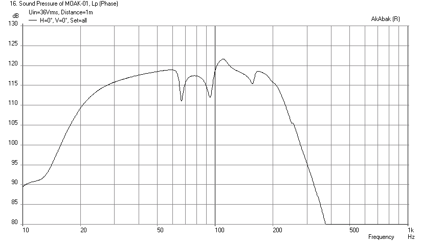
Disregard my earlier post showing the response against a wall - I had a typo in the script. The response is actually better, and here it is with 1.4x scale width, 2.5x scale height and depth, Karlson aperture going to a sharp cusp, with 10 Hz and 200 Hz HPF and LPF, respectively. Note that the new maximum drive voltage is now 36 volts to reach xmax. Speaker is placed up against the wall.

I think you will be happy with this design - no need to EQ as it is +/- 2.5 dB over 20 Hz to 200 Hz.
Disregard my earlier post showing the response against a wall - I had a typo in the script. The response is actually better, and here it is with 1.4x scale width, 2.5x scale height and depth, Karlson aperture going to a sharp cusp, with 10 Hz and 200 Hz HPF and LPF, respectively. Note that the new maximum drive voltage is now 36 volts to reach xmax. Speaker is placed up against the wall.
I think you will be happy with this design - no need to EQ as it is +/- 2.5 dB over 20 Hz to 200 Hz.
Attachments
Unfortunately I could not fit that depth in the space I have available. Will it work it the width and depth are just scaled to 1.4x, and the height scaled to 2.5x? The width and depth will be 596mm W x 632mm D x 1969mm H. If I made the depth 0.95m deep, then I will have no place to put the main front speakers. 😱 So I hope it will work with these dimensions. 🙂
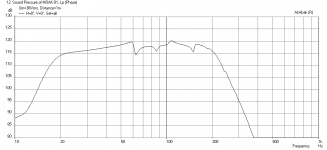
If you scaled the depth by 1.53x you will get the 0.63 meter depth. This is an approximate simulaton of the resulting response. It may still be sufficiently flat for you - I don't know.
Attachments

Zero D,
Thanks! I can't even imagine what that would sound like at those SPLs - my neighbors would call the cops probably. I think at those low frequencies and pressures I would probably feel kind of nauseous actually....
Thanks! I can't even imagine what that would sound like at those SPLs - my neighbors would call the cops probably. I think at those low frequencies and pressures I would probably feel kind of nauseous actually....
Deon,
Are you still good with the predicted response in post 34 for the cabinet that fits your space requirements? Otherwise maybe a tapped horn proper may be what you need.
Are you still good with the predicted response in post 34 for the cabinet that fits your space requirements? Otherwise maybe a tapped horn proper may be what you need.
- Status
- Not open for further replies.
- Home
- Loudspeakers
- Subwoofers
- MOAK: The Mother of All Karlsonators (aka The Magnificent Monster)