I placed an order for the PCBs with JLCPCB late this morning and they're already in production. In looks like the Lunar New Year holiday is winding down. Total cost for 5 boards using the cheapest shipping was US $8.10. A bargain, in my books. I don't think I can even buy perf boards for that.
Now that I'm in the PCB groove, I'm going to make one for the output coupling capacitor array and one for power supply snubbers.
Now that I'm in the PCB groove, I'm going to make one for the output coupling capacitor array and one for power supply snubbers.

According to the JLPCB website, the voltage amplifier PCBs have been fabricated and are ready for delivery.
This morning I placed a new order for the output capacitor bank PCBs and power supply snubber PCBs.
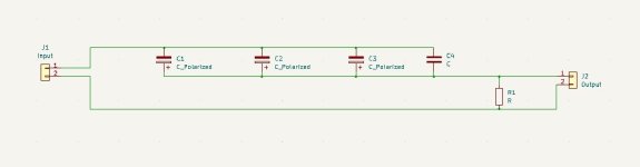
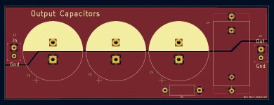
The output capacitor bank PCB contains 3 x 3300uF 160V capacitors and a film bypass capacitor; and a bleeder resistor at the output. The back side of the board is a ground plane.
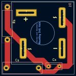
Looking at the snubber PCB now, I see that I could have moved Rs closer to Cs. There's always something ...
This morning I placed a new order for the output capacitor bank PCBs and power supply snubber PCBs.
The output capacitor bank PCB contains 3 x 3300uF 160V capacitors and a film bypass capacitor; and a bleeder resistor at the output. The back side of the board is a ground plane.
Looking at the snubber PCB now, I see that I could have moved Rs closer to Cs. There's always something ...
Attachments
Having built a few similar, I offer caution with regard to reliability vs chip temperature. At 100 watts in single ended Class A you can easily see 100 C. chip temperatures, which approach the death zone. You want to be careful about adequate sinking and ventilation, etc, even with push-pull designs.

Thank you, Nelson, for your expertise and relating your experiences. I am still thinking about the heat issue, so I am grateful for your advice. Actually, I have not powered up the amp since the initial tests because of the temperature concern.Having built a few similar, I offer caution with regard to reliability vs chip temperature. At 100 watts in single ended Class A you can easily see 100 C. chip temperatures, which approach the death zone. You want to be careful about adequate sinking and ventilation, etc, even with push-pull designs.
I have three things that I will do. I will lower the current. That will reduce the heat production. To try to get rid of the heat better, I am going to polish the heatsink under the SIT some more to try to improve the heat transfer to the heatsink. I will also add a fan to the top of the heatsink to pull more air up through the heatsink.
Ultimately, I can drop the power output to a lower value if the attempts at lowering the temperature do not gain significant results. 100 watts output is a nice goal but in the end, it's just a number.
I worked on this gain stage a while ago, so I had to review what I did, but the answer to the low gain is global feedback. I developed this circuit with the intent of using it as a preamp so I didn't want a lot of gain. I just used the same circuit for this amp without a lot of thought, except to check for maximum voltage output.Thank you! And how do you get away with such a low voltage gain?
Now, I'm thinking that I could reduce the feedback and see how that would work. A bit more gain would be handy as a VA stage, although not necessary for my system. My preamp, a choke loaded Sony VFET, has a fair amount of gain.
The last couple of days, I've been working on getting the temperature of the SIT down.
First I looked at the transistor / heatsink interface. The temperature difference at the heatsink compared to the transistor flange with the insulating pad was somewhere around 17 to 20 degrees C. With 130 watts being dissipated, that's about 0.15 degrees C / watt. I didn't think I could improve that significantly.
Next, I tried to lower the quiescent current through the SIT. That worked to some degree, but then power output also dropped significantly. I didn't want to go there yet, so I moved on.
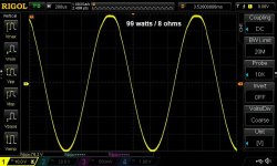
I tried decreasing voltage instead. Using a Variac, I dropped the power supply voltage from about 120V to 97V. I adjusted the quiescent current to 2.40 amps and this got the output power up to over 95 watts into 8 ohms before the sine wave displayed on the oscilloscope showed the start of flattening of the positive phase. Measurements of the SIT showed Vds = 46.8V, with Iq= 2.40A. This works out to a dissipation of 112 watts, which is significantly lower than the previous 130 watts.
Things were moving in the right direction. Another thing that I addressed was increasing the airflow through the heatsink. I added a fan to the top of the heatsink, creating a push - pull system.
Measurement of the SIT showed temperature at the side of the flange just above the heatsink to be just over 50 degrees C. The temperature at the intersection of the flange and the top cover was 60 degrees C. The top part of the case is only in contact with air so that interface has a much higher thermal resistance than the flange which is in contact with the insulating pad and then the heatsink.
I don't know what the thermal resistance of the 2SK182ES junction to case is, but it seems that for a TO-3 case, that number can be as low as 0.8 degrees C / watt. The 2SK182ES's case is quite a bit larger than most TO-3 cases so I'm guessing its junction-case thermal resistance may be lower.
Another thing I'm not clear about is what is the relevant case temperature. Apparently, the point on the case for temperature calculations is the centre of the case flange at the bottom of the case. With the SIT mounted on the heatsink, this is not accessible.
Without an actual measurement of the case temperature at the back of the SIT and no documented junction-case thermal resistance number, I can only estimate the junction temperature based on two numbers with some associated errors. However, I can give it a try and my guess is: (60 + 0.75 x 112) = 144 degrees C. The rated maximum junction temperature is 150 degrees C.
After all these changes, I can touch the SIT side/top of the case with my finger without having to pull my finger off after a time.
The 2SK182ES is rated for a maximum power dissipation of 500 watts. At 112 watts, it's 23% of maximum.
By reducing the power dissipated, lowering the maximum power output, and adding more fan power, this dropped the temperature of the 2SK182ES to a point where it will probably not expire prematurely. However, I will look at adding more cooling fans to try to reduce the case temperature further. There is room at the top of the heatsink for that, and even if I can only lower the SIT temperature a couple of degrees, it will be worth it.
First I looked at the transistor / heatsink interface. The temperature difference at the heatsink compared to the transistor flange with the insulating pad was somewhere around 17 to 20 degrees C. With 130 watts being dissipated, that's about 0.15 degrees C / watt. I didn't think I could improve that significantly.
Next, I tried to lower the quiescent current through the SIT. That worked to some degree, but then power output also dropped significantly. I didn't want to go there yet, so I moved on.
I tried decreasing voltage instead. Using a Variac, I dropped the power supply voltage from about 120V to 97V. I adjusted the quiescent current to 2.40 amps and this got the output power up to over 95 watts into 8 ohms before the sine wave displayed on the oscilloscope showed the start of flattening of the positive phase. Measurements of the SIT showed Vds = 46.8V, with Iq= 2.40A. This works out to a dissipation of 112 watts, which is significantly lower than the previous 130 watts.
Things were moving in the right direction. Another thing that I addressed was increasing the airflow through the heatsink. I added a fan to the top of the heatsink, creating a push - pull system.
Measurement of the SIT showed temperature at the side of the flange just above the heatsink to be just over 50 degrees C. The temperature at the intersection of the flange and the top cover was 60 degrees C. The top part of the case is only in contact with air so that interface has a much higher thermal resistance than the flange which is in contact with the insulating pad and then the heatsink.
I don't know what the thermal resistance of the 2SK182ES junction to case is, but it seems that for a TO-3 case, that number can be as low as 0.8 degrees C / watt. The 2SK182ES's case is quite a bit larger than most TO-3 cases so I'm guessing its junction-case thermal resistance may be lower.
Another thing I'm not clear about is what is the relevant case temperature. Apparently, the point on the case for temperature calculations is the centre of the case flange at the bottom of the case. With the SIT mounted on the heatsink, this is not accessible.
Without an actual measurement of the case temperature at the back of the SIT and no documented junction-case thermal resistance number, I can only estimate the junction temperature based on two numbers with some associated errors. However, I can give it a try and my guess is: (60 + 0.75 x 112) = 144 degrees C. The rated maximum junction temperature is 150 degrees C.
After all these changes, I can touch the SIT side/top of the case with my finger without having to pull my finger off after a time.
The 2SK182ES is rated for a maximum power dissipation of 500 watts. At 112 watts, it's 23% of maximum.
By reducing the power dissipated, lowering the maximum power output, and adding more fan power, this dropped the temperature of the 2SK182ES to a point where it will probably not expire prematurely. However, I will look at adding more cooling fans to try to reduce the case temperature further. There is room at the top of the heatsink for that, and even if I can only lower the SIT temperature a couple of degrees, it will be worth it.
Attachments

Hello pinholer,
good progress! And you 've built a hot soundmachine...
Did you get your FAB-membership (fearless amplifier builder) yet?
Cheers
Dirk
good progress! And you 've built a hot soundmachine...
Did you get your FAB-membership (fearless amplifier builder) yet?
Cheers
Dirk
Maybe if would help to build larger chassis with larger heatsink. Then I think passive cooling can handle it.
A bit like the DAD chassis here:
https://dadbluecat.com/about-us/
or
For the Lazy Singing Bush mono blocks I built I used standard chassis (dissipating 200W pr. mono block. One side can take 100W without any problems):

A bit like the DAD chassis here:
https://dadbluecat.com/about-us/
or
For the Lazy Singing Bush mono blocks I built I used standard chassis (dissipating 200W pr. mono block. One side can take 100W without any problems):
I would go for water cooling at that dissipation level. If air cooling, build a proper wind tunnel. That heat sink has very narrow fins so needs powerful fans (means noisy) to push air through. Water cooling heatsinks combine better with quiet pc fans. Last time I checked, water cooling parts were quite affordable via AliExpress.
Well, Dirk. I'm getting less fearless instead of more fearless, so my membership hopes may be slipping away. I think I'm advancing on the Dunning–Kruger curve, where I realize how much I don't know.Hello pinholer,
good progress! And you 've built a hot soundmachine...
Did you get your FAB-membership (fearless amplifier builder) yet?
Cheers
Dirk

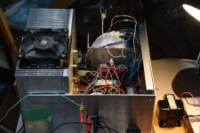
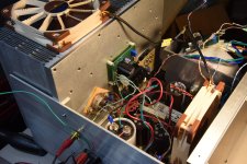
In terms of heatsinking, I think my fan cooled system is working fairly well. You can see it in the picture, if you look closely, that I have a piece of cardboard taped to the open side of the heatsink, helping to create a chimney effect. The actual heatsink temperature at the SIT is fairly low, so I don't think adding more mass or air will offer big improvements.
I could improve the interface between the SIT and heatsink by going without the insulating pad. The SIT drain is at ground (0 volts), but the thermal resistance even with the pad is not super high anyways. But, even though the SIT case is at ground, there is still the ground-loop breaker to deal with. I don't want to have to isolate the heatsink.
My main concern now is the heat difference between the SIT junction and its case. This is a bit of an unknown quantity to me, but this is where water cooling could offer benefits. This has potential to lower the case temperature more efficiently so there is higher heat flow from the junction.
But I think I'm close to the point where the existing system, with some additional fans, may work well enough for me to be comfortable with it.
Would it help blowing air directly at the devices from inside of chassis?
It should be easy to test by handholding a blower and look at the heatsink temperature?
It should be easy to test by handholding a blower and look at the heatsink temperature?
It would help, but I think the thermal resistance for the case to ambient is quite a bit higher than case to heatsink so the heat flow would not increase by much even though the driving force, temperature difference, is higher. It would be more efficient to get more heat from the heatsinks.
I've ordered 4 Noctua 120mm fans, so by having 3 x 90mm diameter on the bottom and 2 x 120mm diameter on the top in a push-pull arrangement, this may be enough cooling. This in theory would move about 382 cubic metres of air per hour. This would be over 30% more than what I have now with the 3 fans below and 1 fan above the heatsink (288 cubic metres / hour).
If I can get the SIT case temperature down by a few more degrees in this way, I will be happy.
Finally, another update.
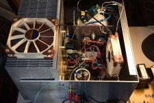
I received some more Noctua cooling fans and I've been trying different configurations. In the end, the best result was to use one on top of the heatsink pulling the air up through the heatsink (supplementing the fans below the heatsink), and another inside the case blowing air onto the SIT.
My temperature measurements at various points of the heatsink and surrounding airspace showed fairly low temperature gradients, which I interpret to mean the heat is flowing well. The differences in temperature between various parts of the heatsink, and the heatsink fins and air, are around 3 degrees to 4 degrees C.
With the present cooling setup, at 113 watts through the 2SK182ES, the hottest part of the SIT case, at the top of the flange, is 60 deg. C. The bottom edge of the flange on the insulation pad is 53 deg. C, while the point on the heatsink underneath the pad is 41 deg. C.
The top of the case at the centre point is 55 deg. C. This is with a fan blowing air onto the SIT.
The big question is what is the junction temperature of the SIT, and without knowledge of the junction to case thermal resistance, I can only guess. I think the junction temperature could be in the 130 deg. to 140 deg. range. One good thing is at 113 watts dissipation, this is only 23% of the 500W maximum power rating. I feel comfortable with this, so I'm going to keep moving forward. The siren's song is hard to resist.
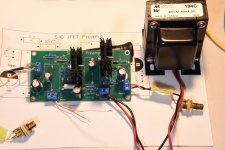
On another front, I received the PCBs for the SiC voltage amplifier. I populated a board with whatever components that I had around, nothing special, and confirmed that the board functioned as I intended. A couple of component footprints could be a little bigger, but not a big problem.
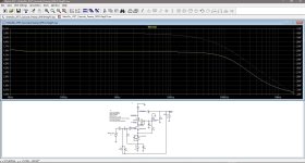
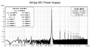
I powered the voltage amp with a makeshift 95V power supply and made a couple of distortion measurements. At 9.0Vpp 1 kHz output, which should drive the output stage to about 1 watt, THD is 0.0015%. At 84Vpp out (100W OS out), THD is 0.0051%. The output stage distortions will be significantly higher so this should work.
More voltage amp tests to come.
I received some more Noctua cooling fans and I've been trying different configurations. In the end, the best result was to use one on top of the heatsink pulling the air up through the heatsink (supplementing the fans below the heatsink), and another inside the case blowing air onto the SIT.
My temperature measurements at various points of the heatsink and surrounding airspace showed fairly low temperature gradients, which I interpret to mean the heat is flowing well. The differences in temperature between various parts of the heatsink, and the heatsink fins and air, are around 3 degrees to 4 degrees C.
With the present cooling setup, at 113 watts through the 2SK182ES, the hottest part of the SIT case, at the top of the flange, is 60 deg. C. The bottom edge of the flange on the insulation pad is 53 deg. C, while the point on the heatsink underneath the pad is 41 deg. C.
The top of the case at the centre point is 55 deg. C. This is with a fan blowing air onto the SIT.
The big question is what is the junction temperature of the SIT, and without knowledge of the junction to case thermal resistance, I can only guess. I think the junction temperature could be in the 130 deg. to 140 deg. range. One good thing is at 113 watts dissipation, this is only 23% of the 500W maximum power rating. I feel comfortable with this, so I'm going to keep moving forward. The siren's song is hard to resist.
On another front, I received the PCBs for the SiC voltage amplifier. I populated a board with whatever components that I had around, nothing special, and confirmed that the board functioned as I intended. A couple of component footprints could be a little bigger, but not a big problem.
I powered the voltage amp with a makeshift 95V power supply and made a couple of distortion measurements. At 9.0Vpp 1 kHz output, which should drive the output stage to about 1 watt, THD is 0.0015%. At 84Vpp out (100W OS out), THD is 0.0051%. The output stage distortions will be significantly higher so this should work.
More voltage amp tests to come.
Attachments

A quick question. What exactly do the snubbers do on the bridge? Would it have any effect on lowering the 120hz spike in your traces or is that just related to the 1khz signal. I am working on lowering 120 hz noise in my Amp with inputs shorted no signal.
Let me correct myself. The 120 hz would not have any relation to the 1khz. So original question holds?
- Home
- Amplifiers
- Pass Labs
- Mo' Power - 100W / 8 ohms From Tokin 2SK182ES SIT? Can't Resist the Siren's Song