So far it's been quite warm in western Canada this winter. But the cold is coming. The amps will definitely augment my home furnace. And it will be 600 watts of heat as each monoblock will be good for 300 watts. At least electricity prices here are not too bad.
I got them off ebay several years ago. I think they were just surplus that someone was clearing out. They are meant for forced air cooling, though, which was what I wanted.
If you're interested in large heatsinks, torontosurplus&scientific on ebay generally has a selection of large heatsinks. Their prices are in Canadian dollars, so when converted to American dollars, the prices are pretty good. Actually, they may be where I bought these heatsinks.
If you're interested in large heatsinks, torontosurplus&scientific on ebay generally has a selection of large heatsinks. Their prices are in Canadian dollars, so when converted to American dollars, the prices are pretty good. Actually, they may be where I bought these heatsinks.
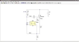
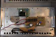
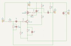
I got the urge to melt some solder last night, so I tackled rewiring the CCS circuit. The BAF 2015 circuit uses an N type MOSFET with a positive power supply, while this amp will use a negative power supply with a P type MOSFET. This requires changing the connections to the 4N37 opto isolator, reversing the polarity of the electrolytic capacitor at the 4N37, and upgrading the power decoupling capacitor to one rated for 200V. I also wanted to add a variable resistor to the MOSFET bias circuit for easy adjustments.
The circuit changes were fairly easy, except for some finicky work unsoldering and resoldering the parts around the 4N37. The little IC pins are quite close together and my eyes are not as good as they used to be.
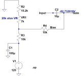
To test the rebuilt circuit, I used a network of power resistors to act as the 2SK182ES SIT for DC tests. LTspice shows Vds = 69.3V with Iq = 2.5A. Using Ohm's Law, a resistor value of 69.3V/2.5A = 27.7 ohms would work. I configured 5 x 8 ohm power resistors to work as the 28 ohm load.
I used my lab power supply (with current limiting) for the initial power on. I started from 0V and went up to about 20V and the circuit behaved normally. From there, I used the new 120V power supply connected to a Variac and continued testing at increasingly higher voltages.
As the supply voltage reached 60V, I noticed that the MOSFET Vgs was tracking too close to Vds and the MOSFET bias was not working correctly. First, I thought maybe the 4N37 had given up, so I replaced it with a new one. That didn't help, and when I did a close inspection of the 4N37 neighbourhood with a magnifying glass and probe, I discovered a poorly soldered joint.
I resoldered the connection at the 4N37 pin and resumed testing. This time, voltage measurements confirmed that the MOSFET was functioning correctly. I increased the supply voltage to 120V and tried to dial in 2.5A through the 28 ohm load resistor. That's when I encountered the next issue. I could not get the current higher than about 2A.
The value of R4 controlling the voltage at the MOSFET gate was too high, so I paralleled a resistor to R4 to bring its value from 10k ohms to 5k ohms. This improved things, but the current was still short of 2.5A. I then increased the value of R5 from 100 ohms to 120 ohms. This was enough to get the current through the load resistor up to 2.5A.
I let the circuit run for about 10 minutes and it appeared to be stable, so I wrapped it up for the night. It was way past my bedtime.
Today, I powered up the circuit again and let it run for about one hour. The heatsink got warm, but not hot enough to bother measuring the temperature. The 3 Noctua 90mm fans are more than adequate for the cooling task. The load power resistors got quite hot, though.
Next up is assembling the 2SK182ES bias circuit. This is quite simple as it is just a voltage divider off the 120V power supply. I may have to tune the CCS circuit a bit more depending on the actual SIT Vds at 2.5A. Right now the assumption is 69V at 2.5A based on the LTspice model.
The circuit changes were fairly easy, except for some finicky work unsoldering and resoldering the parts around the 4N37. The little IC pins are quite close together and my eyes are not as good as they used to be.
To test the rebuilt circuit, I used a network of power resistors to act as the 2SK182ES SIT for DC tests. LTspice shows Vds = 69.3V with Iq = 2.5A. Using Ohm's Law, a resistor value of 69.3V/2.5A = 27.7 ohms would work. I configured 5 x 8 ohm power resistors to work as the 28 ohm load.
I used my lab power supply (with current limiting) for the initial power on. I started from 0V and went up to about 20V and the circuit behaved normally. From there, I used the new 120V power supply connected to a Variac and continued testing at increasingly higher voltages.
As the supply voltage reached 60V, I noticed that the MOSFET Vgs was tracking too close to Vds and the MOSFET bias was not working correctly. First, I thought maybe the 4N37 had given up, so I replaced it with a new one. That didn't help, and when I did a close inspection of the 4N37 neighbourhood with a magnifying glass and probe, I discovered a poorly soldered joint.
I resoldered the connection at the 4N37 pin and resumed testing. This time, voltage measurements confirmed that the MOSFET was functioning correctly. I increased the supply voltage to 120V and tried to dial in 2.5A through the 28 ohm load resistor. That's when I encountered the next issue. I could not get the current higher than about 2A.
The value of R4 controlling the voltage at the MOSFET gate was too high, so I paralleled a resistor to R4 to bring its value from 10k ohms to 5k ohms. This improved things, but the current was still short of 2.5A. I then increased the value of R5 from 100 ohms to 120 ohms. This was enough to get the current through the load resistor up to 2.5A.
I let the circuit run for about 10 minutes and it appeared to be stable, so I wrapped it up for the night. It was way past my bedtime.
Today, I powered up the circuit again and let it run for about one hour. The heatsink got warm, but not hot enough to bother measuring the temperature. The 3 Noctua 90mm fans are more than adequate for the cooling task. The load power resistors got quite hot, though.
Next up is assembling the 2SK182ES bias circuit. This is quite simple as it is just a voltage divider off the 120V power supply. I may have to tune the CCS circuit a bit more depending on the actual SIT Vds at 2.5A. Right now the assumption is 69V at 2.5A based on the LTspice model.
Attachments
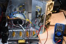

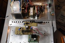
My bargain chokes arrived yesterday so I finished the power supply. I added another LC filter consisting of a Hammond 159ZE (29 mH, 430 mohm) choke and 3.3 mF capacitor. Total power supply filtration is: 11mF - 10mH - 11mF - 29mH - 3.3mF. According to PSUD II, this should bring the ripple to about 0.39 mV peak-to-peak.
I load tested the completed power supply with my 28 ohm resistor array and the output voltage stabilized at just over 120 volts.
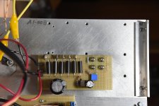
Over the last few days, I also built the SIT bias circuit on perf board. This will divide the 120 volt power supply to provide biasing for the SIT. Besides the connection to PS negative and ground, it connects the input signal to the DC blocking capacitor and through to the SIT gate (with the bias voltage).
The amp is now mostly complete. I just need to install the 2SK182ES, the output coupling capacitors, and some wiring. The moment of truth is coming ...
I load tested the completed power supply with my 28 ohm resistor array and the output voltage stabilized at just over 120 volts.
Over the last few days, I also built the SIT bias circuit on perf board. This will divide the 120 volt power supply to provide biasing for the SIT. Besides the connection to PS negative and ground, it connects the input signal to the DC blocking capacitor and through to the SIT gate (with the bias voltage).
The amp is now mostly complete. I just need to install the 2SK182ES, the output coupling capacitors, and some wiring. The moment of truth is coming ...
Attachments

Going back to basics, why build a highly powered pure class A amp over one that does eg the first 30-50W in class A and then goes into AB to 100/150W? The extra watts are only used for dynamic peaks or some low frequency rumble, not sure they need to be at the highest quality?
Audio does not necessarily follow logic for some people. Like me. Especially DIY. I actually don't need this amp. I've already got more amps than I need. However, I haven't seen any 100 watt SIT amps, so I thought I would try to build one. There is no real justification from a logical point of view. But then, I'm not Spock.
Sure, understood, but why not build a 200W AB amp, or whatever the max for the SK182 is, with 30W in class A? I believe the PassLab amps also go that way.
It's about the heat, danger, fear, and excitement. Bungy jumping for the nerds. Also trying to get my FAB merit badge.
Ok. I think only amps with either a B+ >=1kV or which require a 3-phase supply qualify for that set of adjectives 😎heat, danger, fear, and excitement
It's the fear of taking the lives of the silicon critters that gets my adrenaline pumping. Not quite WE 300B class, but they are close enough to me.
And the power supply can pump out 5 amps at 120 volts. Probably 10 amps or more for a short period of time.
And the power supply can pump out 5 amps at 120 volts. Probably 10 amps or more for a short period of time.
Sure, understood, but why not build a 200W AB amp
What is wise, sensible, ”enough”, and sane has nothing to do with it. This is for fun, adventure, experimentation, learning and curiosity, according to me - This amplifier building and speaker building, and home theater building thing.
A really, really good and convenient choice is Airpods Pro noise cancelling earphones, an Iphone, and a Tidal/Spotify subscription: If all you need is ONLY really, really good sound and all the music in the world.
But, for me. Its simply just not that cheap, wise, sensible and simple…
🙂🙂🙂
And…You can not feel the bass with earphones.
🎸🙂🎺
No one needs a Bugatti Veyron, Ferrari F-40, or Koenigsegg Jesko either, and unfortunately I can't afford one. 🤓
That is well beneath my expectations for an audiophile system, but then I am not really a headphone person. Sounds more like a good consumer sound system.Airpods Pro noise cancelling earphones, an Iphone, and a Tidal/Spotify subscription
I don’t mind the overkill at all, the extra headroom adds scale, presence etc, but I am merely wondering whether a very highly biased A/AB wouldn’t achieve more cojones due to higher peak output capability.
Success!
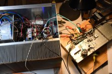
I got the output stage wired up yesterday and verified that it was functioning properly. Today, I wanted to see if this thing can actually put out 100 watts. I added the United SiC JFET voltage amplifier stage, and fed it all with my Acurus L10 preamp to get the needed gain.
Initial trials topped out at about 30 watts into 8 ohms with clipping observed. The problem was too much Vgs which limited the current (2 amps) and also resulted in a high Vds (85 volts). This caused very high SIT case temperatures. I measured about 105 degrees C. That certainly concerned me.
My bias circuit was adjusted for minimum Vgs in its range and that was too high. I modified the voltage divider values to get a lower negative bias voltage range. This allowed me to set an operating point of 57.8 Vds and Iq of 2.5A. This is about 145 watts of power dissipated, and the SIT temperature was much lower at 73 degrees C.
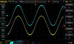
With these changes, I was able to get 84V peak-to-peak into 8 ohms before clipping was evident on the oscilloscope. That works out to 111 watts.
I was very happy to see the oscilloscope waveform reach 80Vpp and beyond without clipping!
I got the output stage wired up yesterday and verified that it was functioning properly. Today, I wanted to see if this thing can actually put out 100 watts. I added the United SiC JFET voltage amplifier stage, and fed it all with my Acurus L10 preamp to get the needed gain.
Initial trials topped out at about 30 watts into 8 ohms with clipping observed. The problem was too much Vgs which limited the current (2 amps) and also resulted in a high Vds (85 volts). This caused very high SIT case temperatures. I measured about 105 degrees C. That certainly concerned me.
My bias circuit was adjusted for minimum Vgs in its range and that was too high. I modified the voltage divider values to get a lower negative bias voltage range. This allowed me to set an operating point of 57.8 Vds and Iq of 2.5A. This is about 145 watts of power dissipated, and the SIT temperature was much lower at 73 degrees C.
With these changes, I was able to get 84V peak-to-peak into 8 ohms before clipping was evident on the oscilloscope. That works out to 111 watts.
I was very happy to see the oscilloscope waveform reach 80Vpp and beyond without clipping!
Attachments

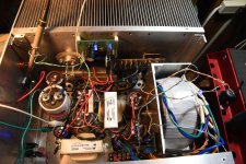
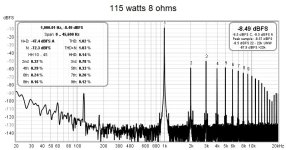
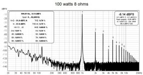
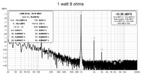
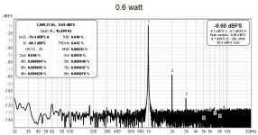
I did some distortion tests today. The results, into 8 ohms, are:
0.6w ___ 0.040%
1w _____ 0.054%
25w ____ 0.27%
57w ____ 0.47%
100w ___ 0.70%
115w ___ 1.02%
I measured the 0.6w output without the JFET voltage amplifier. The maximum output of the 1 kHz oscillator was wired direct to the 2SK182ES output stage.
The measurements at 1w and higher included the JFET voltage amplifier and Acurus preamp. The increased 120 Hz noise is evident. This is due to the poor wiring technique of the prototype.
Next up is producing a proper printed circuit board for the voltage amplifier.
Attachments

After some more burn in testing of the amplifier, I found then when not operating at full power, the Tokin SIT temperature started to rise and approached just over 100 degrees C. In hind sight, this is not surprising, since during max power tests, the 8 ohm fan cooled heatsinked load resistor was getting very hot. When the amp is idling, that energy is dissipated by the MOSFET and SIT instead.
The heatsink was just not up to dissipating 300 watts. The fins are too thin so there is high thermal resistance between it and the heatsink base, and the heat was not flowing into the fins. The heatsink was good for 120 watts with the BAF amp, but 300 watts is just too much.
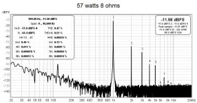
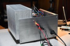
This idea of building a high powered class A SIT amplifier had been in my brain for a while, and about a year and a half ago, I made the first move by purchasing a pair of huge heatsinks, I'm glad I did because now they are just what I need.
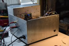
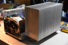
These heatsinks are huge (12'' x 9'' x 5'') and weigh about 20 lbs (9 kg). They are the same ones that Ben Mah uses in his room heater amps. So, I drilled and tapped and installed one of these huge heatsinks into the amp chassis. It's a real mash-up now, but it is functional. Later, I will replace the chassis front, back, and side panels to match the heatsink height.
With the new heatsink in place, cooled with the three Noctua 92mm computer fans, I began temperature testing again. The SIT case temperature was lower but was still approaching 100 degrees C. Not good.
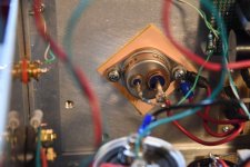
I suspected that the thermal pad under the SIT was not passing the heat well. I was using a pad material that I had received with my SITs. I don't know what the material is or its thermal resistance, but I thought this pad might be the problem. Luckily, I had some Wakefield-Vette pads that I purchased from Digikey. So, I replaced the questionable pad with a Wakefield-Vette pad and continued my testing.
The results were much better. The temperature of the SIT at the junction of the flanged base and top cap was 87 degrees C; at the junction of the SIT and heatsink, on the thermal pad was 72 degrees C; and the temperature at the very top of the heatsink fins was 46 degrees C. I could touch the SIT case with my finger for about 2 seconds.
With the fans in action, I can definitely feel the heat coming off the heatsink. The difference was noticeable. Two amps would heat a room nicely.
The Tokin 2SK182ES is rated for 500 watts of dissipation and I'm running at 150 watts. That's 30% of maximum and I think that is acceptable. The one thing that I don't know is the junction to case thermal resistance so I can only guess at the junction temperature. The maximum rating is 150 degree C. I suspect I'm up there.
As I'm writing this, it occurred to me that I had not raised the amp sufficiently off the table to allow the fans free access to air. The fans blow air up from the bottom of the heatsink. The chassis feet are only 1/2 inch high and the fans, at 1/2 inch above the table, cannot work at full capacity with the restricted access to incoming air. I had discovered that in my previous tests.
After blocking up the feet so there was one inch between the fans and the table below, I redid the temperature measurements:
Temperature - Deg. C
Clearance
0.5" .... 1" Location
87 ___ 77 junction of the flanged base and top cap
72 ___ 64 junction of the SIT and heatsink, on the thermal pad
46 ___ 35 top of heatsink fins
The maximum temperature on the SIT case is now 77 degrees C compared to 87 degrees C when the air flow to the fan was restricted. The temperature is a bit on the high side, but I think I can live with that.
The heatsink was just not up to dissipating 300 watts. The fins are too thin so there is high thermal resistance between it and the heatsink base, and the heat was not flowing into the fins. The heatsink was good for 120 watts with the BAF amp, but 300 watts is just too much.
This idea of building a high powered class A SIT amplifier had been in my brain for a while, and about a year and a half ago, I made the first move by purchasing a pair of huge heatsinks, I'm glad I did because now they are just what I need.
These heatsinks are huge (12'' x 9'' x 5'') and weigh about 20 lbs (9 kg). They are the same ones that Ben Mah uses in his room heater amps. So, I drilled and tapped and installed one of these huge heatsinks into the amp chassis. It's a real mash-up now, but it is functional. Later, I will replace the chassis front, back, and side panels to match the heatsink height.
With the new heatsink in place, cooled with the three Noctua 92mm computer fans, I began temperature testing again. The SIT case temperature was lower but was still approaching 100 degrees C. Not good.
I suspected that the thermal pad under the SIT was not passing the heat well. I was using a pad material that I had received with my SITs. I don't know what the material is or its thermal resistance, but I thought this pad might be the problem. Luckily, I had some Wakefield-Vette pads that I purchased from Digikey. So, I replaced the questionable pad with a Wakefield-Vette pad and continued my testing.
The results were much better. The temperature of the SIT at the junction of the flanged base and top cap was 87 degrees C; at the junction of the SIT and heatsink, on the thermal pad was 72 degrees C; and the temperature at the very top of the heatsink fins was 46 degrees C. I could touch the SIT case with my finger for about 2 seconds.
With the fans in action, I can definitely feel the heat coming off the heatsink. The difference was noticeable. Two amps would heat a room nicely.
The Tokin 2SK182ES is rated for 500 watts of dissipation and I'm running at 150 watts. That's 30% of maximum and I think that is acceptable. The one thing that I don't know is the junction to case thermal resistance so I can only guess at the junction temperature. The maximum rating is 150 degree C. I suspect I'm up there.
As I'm writing this, it occurred to me that I had not raised the amp sufficiently off the table to allow the fans free access to air. The fans blow air up from the bottom of the heatsink. The chassis feet are only 1/2 inch high and the fans, at 1/2 inch above the table, cannot work at full capacity with the restricted access to incoming air. I had discovered that in my previous tests.
After blocking up the feet so there was one inch between the fans and the table below, I redid the temperature measurements:
Temperature - Deg. C
Clearance
0.5" .... 1" Location
87 ___ 77 junction of the flanged base and top cap
72 ___ 64 junction of the SIT and heatsink, on the thermal pad
46 ___ 35 top of heatsink fins
The maximum temperature on the SIT case is now 77 degrees C compared to 87 degrees C when the air flow to the fan was restricted. The temperature is a bit on the high side, but I think I can live with that.
Attachments
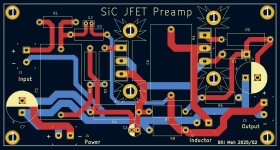
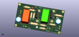
I've got the PCB design for the United SiC power JFET voltage amplifier (preamp) pretty well finished. I can probably leave it as is, but since JLCPCB is still on holidays until the weekend, I may still tinker with the layout a bit.
The PCB will be 114 mm x 60 mm, so it shouldn't be very expensive to produce. There are provisions for heatsinking the JFET and MOSFET which is a good idea since they each dissipate several watts. The footprint for the coupling capacitors is 32mm x 17mm, so some decent film capacitors can be used.
The PCB will be 114 mm x 60 mm, so it shouldn't be very expensive to produce. There are provisions for heatsinking the JFET and MOSFET which is a good idea since they each dissipate several watts. The footprint for the coupling capacitors is 32mm x 17mm, so some decent film capacitors can be used.
Attachments
- Home
- Amplifiers
- Pass Labs
- Mo' Power - 100W / 8 ohms From Tokin 2SK182ES SIT? Can't Resist the Siren's Song