Amplifier lottery
I’ve been envious of several of my friends who own Pass Amps. I would look forward to getting one however necessary to compare with my McIntosh vintage tubes...or replace!
I’ve been envious of several of my friends who own Pass Amps. I would look forward to getting one however necessary to compare with my McIntosh vintage tubes...or replace!
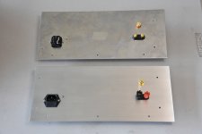
Today, I finished the back panels for the cases. Luckily, not much cursing involved in making the cut-outs for the IEC connectors. Problem with mono-blocks is that there are two cut-outs to make. I drilled holes in each corner, then used a power scrollsaw to cut from hole to hole, and finished off with a file. Not perfect, but the socket hides the imperfections.
A stepped drill bit was used to make the 1/2" holes needed for the input jacks and speaker connectors. Piece of cake.
I also added a screw in each back panel for attaching a safety ground wire. It will only be used for connecting to the power line ground. The amplifier ground will have its own chassis connection.
Finally, I sanded the panels with 200 grit sandpaper to remove scratches and finished off with 400 grit. Then I used a plastic scouring pad to give a nice smooth surface. All sanding was done in one direction, parallel to the long edge of the panel.
Lastly, I applied a coat of oil to the surface to protect it from oxidation. For this, I used extra virgin olive oil from Italy. I found that this protects the aluminum and gives the amplifier a free flowing sound, with good rhythm and pace. I have yet to try first pressing olive oil which I think would be even better.
Attachments

Luckily, not much cursing involved in making the cut-outs for the IEC connectors. .... I drilled holes in each corner, then used a power scrollsaw to cut from hole to hole, and finished off with a file. Not perfect, but the socket hides the imperfections.
I'm with you, every piece needs an IEC, seems more buttoned up that way. I've done mine with a diamond cut-off wheel (~1"?) attached to a cheap 'dremel" tool, along the flats after some small holes in the corners. Careful, it goes like butter! Clean it up with a small flat file and hide it all. Mission accomplished.
Last edited:
I have tried Dremel cutting disks but never a diamond cutting wheel. I use 1/8 inch aluminum plate and the disks I've tried do not cut this well. Mind you, these disks are cheap compared to a diamond one. No free lunches! Maybe I'll spring for a diamond wheel. Everyone needs a diamond.
Lastly, I applied a coat of oil to the surface to protect it from oxidation. For this, I used extra virgin olive oil from Italy. I found that this protects the aluminum and gives the amplifier a free flowing sound, with good rhythm and pace. I have yet to try first pressing olive oil which I think would be even better.
 Good choice! next time just add some drops of Aceto Balsamico and you wil obtain a more wide and deep soundstage! 😀
I've moved from case fabrication to electronic circuit building. The cases aren't totally finished yet, but I want to build the sub-circuits so I can figure out how to lay them out on the case bottom plate. That way, hopefully, I can drill all the holes in the bottom plates in one go.
First up was to work out the snubber resistors for the transformers. There are three power transformers in each amp: V+ and bias for the 2SK180, and V+ for the 2SJ28. So, I dragged out my Quasimodo test jig and oscilloscope and got to work. I tested all the transformers although I probably only needed to test one of each, but I like being thorough.
Antek AS-3216: 2x16V in series, 300VA Rs = 34 ohms
Triad FD6-120: 120V @ 0.25A Rs = 980 ohms
Triad F-113x: 12V @ 0.15A Rs = 180 ohms
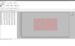
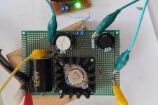
After being hunched over the workbench, twiddling the snubber test potentiometer and oscilloscope knobs, my back was getting sore, but I figured that a whiff or two of solder smoke would fix that up. So, I built one power supply module for the 2SJ28 voltage amplifier. The finished power supply will be CRCRC but the final RC filter will be on the 2SJ28 circuit board so the board that I finished included the snubbing components: rectifier bridge, CRC filter, and a LED power indicator.
I tested the completed module with a 6k ohm load and the supply output was 184V which works out to be about 30mA. I expect the final current draw to be about 40mA. Connected to the oscilloscope, the displayed ripple is a bit more than PSUD predicts, but I'm not worried. The 30H choke load on the 2SJ28 will reject a lot of ripple, and I can also change the filter parameters if necessary.
I started on a new one pound roll of solder today after my last one pound roll, which I bought sometime in the 1980s, finally ran out. The new solder doesn't seem to produce as much smoke, so I don't know whether I should be disappointed or not. Soldering is not the same experience anymore.
First up was to work out the snubber resistors for the transformers. There are three power transformers in each amp: V+ and bias for the 2SK180, and V+ for the 2SJ28. So, I dragged out my Quasimodo test jig and oscilloscope and got to work. I tested all the transformers although I probably only needed to test one of each, but I like being thorough.
Antek AS-3216: 2x16V in series, 300VA Rs = 34 ohms
Triad FD6-120: 120V @ 0.25A Rs = 980 ohms
Triad F-113x: 12V @ 0.15A Rs = 180 ohms
After being hunched over the workbench, twiddling the snubber test potentiometer and oscilloscope knobs, my back was getting sore, but I figured that a whiff or two of solder smoke would fix that up. So, I built one power supply module for the 2SJ28 voltage amplifier. The finished power supply will be CRCRC but the final RC filter will be on the 2SJ28 circuit board so the board that I finished included the snubbing components: rectifier bridge, CRC filter, and a LED power indicator.
I tested the completed module with a 6k ohm load and the supply output was 184V which works out to be about 30mA. I expect the final current draw to be about 40mA. Connected to the oscilloscope, the displayed ripple is a bit more than PSUD predicts, but I'm not worried. The 30H choke load on the 2SJ28 will reject a lot of ripple, and I can also change the filter parameters if necessary.
I started on a new one pound roll of solder today after my last one pound roll, which I bought sometime in the 1980s, finally ran out. The new solder doesn't seem to produce as much smoke, so I don't know whether I should be disappointed or not. Soldering is not the same experience anymore.
Attachments


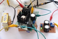
I have made more progress on the electronics over the last few days. I finished the second 2SJ28 power supply and started building the 2SJ28 voltage amplification modules.
I have two 2SJ28s which I had matched for Vgs at 20V Vds and 1A current. They are quite evenly matched with Vgs of 6.35V and 6.40V.
My design is quite simple - it is self biased with a choke load. The choke is a Hammond 157G, rated at 30H, 40mA.
I finished one board and did some testing. I had to adjust the source resistance to 400 ohms after tests in order to reach my design operating point. The final operating parameters are:
V+ = -180V
Vd = -163V
Vs = -14.8V
This works out to:
Vds = -163V - -14.8V = -148V
Vgs = 14.8V
Iq = 14.8V / 400ohms = 37 mA
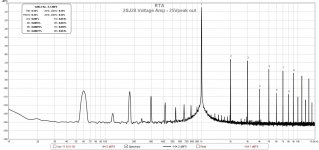
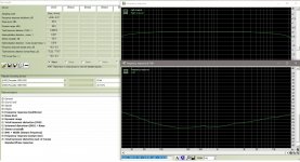
Attached are some test results. The distortion figures are as expected. They are significantly below 0.1% until around 20Vpeak where they are at about 0.1% and by 25Vpeak, the distortion is rising quickly.
One thing that surprised me is the gain. I expected it to be around 10x, but what I got was in the low 20s. I don't have curves for the 2SJ28 at high voltages although I have seen ones for the 2SK82. I also have implemented 2SK82 voltage gain stages in my Luminaria and my 2SK82-2SJ28 amp and the gains there are in the range of 10x. I've checked my test setup and I don't see any errors, but maybe I've missed something.
Next, I'll build another one for the other channel and see how they compare.
I have two 2SJ28s which I had matched for Vgs at 20V Vds and 1A current. They are quite evenly matched with Vgs of 6.35V and 6.40V.
My design is quite simple - it is self biased with a choke load. The choke is a Hammond 157G, rated at 30H, 40mA.
I finished one board and did some testing. I had to adjust the source resistance to 400 ohms after tests in order to reach my design operating point. The final operating parameters are:
V+ = -180V
Vd = -163V
Vs = -14.8V
This works out to:
Vds = -163V - -14.8V = -148V
Vgs = 14.8V
Iq = 14.8V / 400ohms = 37 mA
Attached are some test results. The distortion figures are as expected. They are significantly below 0.1% until around 20Vpeak where they are at about 0.1% and by 25Vpeak, the distortion is rising quickly.
One thing that surprised me is the gain. I expected it to be around 10x, but what I got was in the low 20s. I don't have curves for the 2SJ28 at high voltages although I have seen ones for the 2SK82. I also have implemented 2SK82 voltage gain stages in my Luminaria and my 2SK82-2SJ28 amp and the gains there are in the range of 10x. I've checked my test setup and I don't see any errors, but maybe I've missed something.
Next, I'll build another one for the other channel and see how they compare.
Attachments


Is this somewhat akin to a larger version of Papa's Sony VFET, but instead using all VFETs, and obtaining much more wattage?
As someone who has a pair of 2SK182's, and a pair of 2SK180's on the way as backup, this project really intrigues me. Being able to take advantage of all 4 simultaneously would be cool. 🙂
Although, I have high sensitivity speakers, and likely won't need that much power, it's nice to have possibilities.
This amp that I built, 2SK82 -2SJ28 SE Amp, is quite similar to Mr. Pass' VFET amp. It has a 2SJ28 source follower output stage, like the Pass amp, but uses a 2SK82 voltage amp instead of a step-up transformer for voltage gain.
This new amp is a higher powered take on that previous design with some differences. The 2SK180 follower output will have an inductor load instead of a CCS. Also, I'm using a 2SJ28 for a voltage amp instead of a 2SK82. The choke for the voltage amp is also different; it is a larger Hammond choke so I can run at a higher current.
As far as using one of your SITs for a voltage amp, that would be interesting. Don't know if anybody has used a Tokin SIT at high voltage/low current as a voltage amp. But that is what's great about DIY. It's an opportunity to explore new territory.
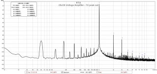
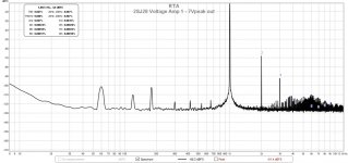
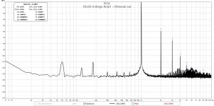
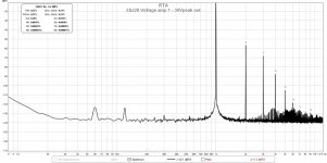
I finished my second 2SJ28 voltage amp module today and ran it through some tests. This VFET, although having very similar Vgs (6.40V vs 6.35V) as the first one, has a lower gain. It is approximately 16 vs the other one at about 21. The resulting in-circuit operating point is also slightly different with Iq = 37mA vs 42mA.
I measured the distortion of the new amp board and found that it had higher distortion than the first one. I went back and remeasured the first one, but could not replicate the lower distortion results from the other day. I admit my test setup is rather haphazard so I guess it is not too surprising. Because the test units are configured with clip-leads with wires all over the place, it is difficult to get consistent results. I use a Focusrite 2i2, 2nd Gen, for analog to digital conversion and it is sensitive to setup with regards to input levels as well.
However, it is not all bad as I found that I could get at least to 30Vpeak (or 60Vpeak-peak) output with still reasonable results. Previously, 25Vpeak output was showing increased higher order distortion.
The FFT results from both channels were remarkably similar, so I am only showing the results from one channel.
Attachments

I'm not qualified to answer that, ZM. You would certainly be a better judge than me. Maybe, if I add another green LED?
with all these VFets, you certainly don't need help of green leds, to achieve necessary level of beauty
🙂
🙂
Today, I finished the back panels for the cases. Luckily, not much cursing involved in making the cut-outs for the IEC connectors. Problem with mono-blocks is that there are two cut-outs to make. I drilled holes in each corner, then used a power scrollsaw to cut from hole to hole, and finished off with a file. Not perfect, but the socket hides the imperfections.
A stepped drill bit was used to make the 1/2" holes needed for the input jacks and speaker connectors. Piece of cake.
I also added a screw in each back panel for attaching a safety ground wire. It will only be used for connecting to the power line ground. The amplifier ground will have its own chassis connection.
Finally, I sanded the panels with 200 grit sandpaper to remove scratches and finished off with 400 grit. Then I used a plastic scouring pad to give a nice smooth surface. All sanding was done in one direction, parallel to the long edge of the panel.
Lastly, I applied a coat of oil to the surface to protect it from oxidation. For this, I used extra virgin olive oil from Italy. I found that this protects the aluminum and gives the amplifier a free flowing sound, with good rhythm and pace. I have yet to try first pressing olive oil which I think would be even better.
Yup, I find any sort of shaped (IEC inlets) holes a pain in the 🙁 but an assortment of hand files and a jigsaw gets me spot on every time.
Regards,
Dan 🙂
P.S. Nice work!
- Home
- Amplifiers
- Pass Labs
- Mo' Chokes: Building 2SJ28 - 2SK180 Monoblocks