I have completed preparation of the bottom plate of one case. All the component mounting holes have been drilled and tapped, and ventilation holes have been added as well. I used this drilled bottom plate as a template to mark the plate for the second monoblock, so that one will be quicker to complete.
Everything went fairly smoothly, except I broke my 4-40 tap after tapping only a couple of holes. The 4-40 taps are so small that an unintended sideways movement was enough to snap it. Quick trip into town and luckily, I was able to buy a new one.
I like to tap the bottom plate screw holes since it makes assembly (or disassembly) much easier. No need to reach under the plate to hold the nut or screw. You can place screws from the bottom so they stick up above the bottom plate and use them as a mounting studs, which I have done before, or screw down into the tapped holes.
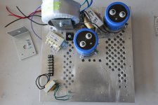
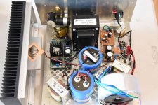
I mounted the components for the main power supply to the plate and it is ready for wiring. I used a Simpson Strong Tie A24 angle (available at hardware stores) for mounting the toroid transformer vertically. This is an easy-to-find alternative to a specially made toroid transformer mounting bracket. Credit goes to Ben Mah for this idea.
The Strong Tie angle is made of mild steel so it is easy to drill mounting holes for attaching to the the bottom plate. I'm hoping that the steel will provide some magnetic shielding as well.
Next step is to wire up the power supply.
Everything went fairly smoothly, except I broke my 4-40 tap after tapping only a couple of holes. The 4-40 taps are so small that an unintended sideways movement was enough to snap it. Quick trip into town and luckily, I was able to buy a new one.
I like to tap the bottom plate screw holes since it makes assembly (or disassembly) much easier. No need to reach under the plate to hold the nut or screw. You can place screws from the bottom so they stick up above the bottom plate and use them as a mounting studs, which I have done before, or screw down into the tapped holes.
I mounted the components for the main power supply to the plate and it is ready for wiring. I used a Simpson Strong Tie A24 angle (available at hardware stores) for mounting the toroid transformer vertically. This is an easy-to-find alternative to a specially made toroid transformer mounting bracket. Credit goes to Ben Mah for this idea.
The Strong Tie angle is made of mild steel so it is easy to drill mounting holes for attaching to the the bottom plate. I'm hoping that the steel will provide some magnetic shielding as well.
Next step is to wire up the power supply.
Attachments


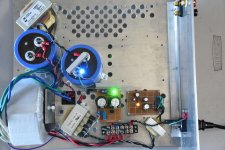
Great 🙂Here's a preliminary layout of the electronics in the case..
One suggestion:
Change position of the one big blue cap close to heatsink with L choke position ?
Capacitors dont like heat so you get longer life span if more distance..Have fun
Good suggestion, Soundhappy. My thinking was to keep the chokes as far away from the amplification components as possible. But you're right. I need to consider heat as well.
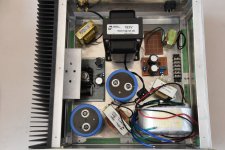
I switched the locations of a filter capacitor and choke as suggested by Soundhappy and completed wiring up the power supply. I tested it at various stages during construction so I would not be surprised when the wiring was complete.
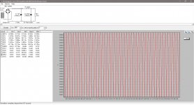
I tested the power supply with a 1.5k ohm load/bleeder resistor. With this load, the output voltage was 45V which is about what I expected. Under the design load of about 2.2A, the voltage should drop to about 40V.
The power transformer is an Antek AS-3216, 300VA with 2x16V secondaries connected in series. Snubber resistor and capacitors were added at the primary side of the rectifier bridge. The supply filter is CLC (50mF-10mH-50mF). I will have an additional RC filter stage near the 2SK180. The PSUD2 simulation predicts ripple at the millivolt level.
Attachments

FUN😀tastic
Diameter size of the psu wires is important..high currents..
maybe from the bridge to caps can be useful get thicker ones ?
The same like Antek wires..
Your mono blocks construction looks great Have a nice day
Diameter size of the psu wires is important..high currents..
maybe from the bridge to caps can be useful get thicker ones ?
The same like Antek wires..
Your mono blocks construction looks great
Have a nice dayThanks for the nice comments.
I use 18 gauge solid copper wire for my power supply because I have a supply of it, it is easy to handle, and its resistance per foot is around 6 milliohms. For short distances, it is not too bad. I've used it in all of my builds and it has worked well. Thicker wire would be better, but even with ripple currents of 15A, the voltage drop to the rectifier is less than 0.1V.
I use 18 gauge solid copper wire for my power supply because I have a supply of it, it is easy to handle, and its resistance per foot is around 6 milliohms. For short distances, it is not too bad. I've used it in all of my builds and it has worked well. Thicker wire would be better, but even with ripple currents of 15A, the voltage drop to the rectifier is less than 0.1V.
I have been using TL431 regulated variable power supplies for bias in my previous amps, but for the choke loaded 2SK180, I was not sure whether it would be the best. Since the choke loaded 2SK180 follower has some self bias due to the source resistance of the choke, the required bias voltage to the gate is lowered. Usually, I use the TL431 as a variable voltage regulator but it it is limited to 2.5V output as its lower limit. With the self bias due to the choke, 2.5V to the gate may still be too high. I could use a voltage divider at its output, but if I was to do that, then I wanted to look other approaches.
I was also aware that it is best not to have a regulated bias supply when the power supply to the SIT's drain is not regulated. This can lead to bias problems if the line voltage varies; Vds will change while Vgs stays fixed. The source resistance of the choke helps, though. So, this was another factor to consider.
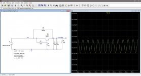
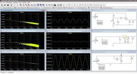
So, what to do? I needed more data, so I used LTSpice to simulate ripple reduction and output noise for a LM317 regulator, a zener/transistor regulator, and a capacitance multiplier to get an idea of the relative performances. The capacitance multiplier, while worst in ripple reduction, had the best noise performance. But everything is a compromise, so you gotta pick what's important to you.
I'm always willing to try new things, so I decided to give the unregulated bias supply a try. Using a brute force approach of CRCRC filtering can achieve very low ripple, but it comes with high RC time constants which means that the bias voltage will ramp up slower that the Vds. With SITs, it is important to have adequate gate voltage at all times to control current.
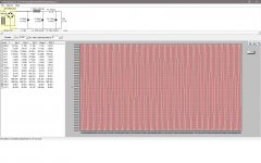
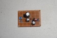
I used a modest CRC filter after the bridge rectifier and finished off with a capacitance mulitplier. This allowed the filter capacitors to charge quickly and still have low ripple at the output. Ripple after the 1000uF - 200 ohm - 220uF filter is in the order of a few millivolts according to PSUD2, and after the capacitance multiplier, ripple is reduced to a few tens of microvolts, according to LTSpice.
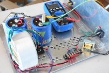
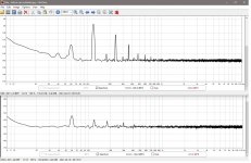
I tried to measure the ripple in the finished capacitance multiplier power supply on my Rigol oscilloscope and could not distinguish the results from that of the shorted oscilloscope probe. I then used my computer to perform FFT analysis of the input versus output of the capacitance multiplier and the results show the ripple reduction. The 120 Hz ripple and its harmonics are significantly reduced as well as the 60 Hz noise. I don't know the actual values but the comparison is informative.
Of course, the real test will be when it is put into use. The proof of the pudding is in the eating.
I was also aware that it is best not to have a regulated bias supply when the power supply to the SIT's drain is not regulated. This can lead to bias problems if the line voltage varies; Vds will change while Vgs stays fixed. The source resistance of the choke helps, though. So, this was another factor to consider.
So, what to do? I needed more data, so I used LTSpice to simulate ripple reduction and output noise for a LM317 regulator, a zener/transistor regulator, and a capacitance multiplier to get an idea of the relative performances. The capacitance multiplier, while worst in ripple reduction, had the best noise performance. But everything is a compromise, so you gotta pick what's important to you.
I'm always willing to try new things, so I decided to give the unregulated bias supply a try. Using a brute force approach of CRCRC filtering can achieve very low ripple, but it comes with high RC time constants which means that the bias voltage will ramp up slower that the Vds. With SITs, it is important to have adequate gate voltage at all times to control current.
I used a modest CRC filter after the bridge rectifier and finished off with a capacitance mulitplier. This allowed the filter capacitors to charge quickly and still have low ripple at the output. Ripple after the 1000uF - 200 ohm - 220uF filter is in the order of a few millivolts according to PSUD2, and after the capacitance multiplier, ripple is reduced to a few tens of microvolts, according to LTSpice.
I tried to measure the ripple in the finished capacitance multiplier power supply on my Rigol oscilloscope and could not distinguish the results from that of the shorted oscilloscope probe. I then used my computer to perform FFT analysis of the input versus output of the capacitance multiplier and the results show the ripple reduction. The 120 Hz ripple and its harmonics are significantly reduced as well as the 60 Hz noise. I don't know the actual values but the comparison is informative.
Of course, the real test will be when it is put into use. The proof of the pudding is in the eating.
Attachments
Last edited:
if properly filtered, biasing circuit is not critical
gain of the stage is low/none .........
as example- LM317 reg folowed with resistive divider for bias voltage , used in Singing Bush, is good enough
gain of the stage is low/none .........
as example- LM317 reg folowed with resistive divider for bias voltage , used in Singing Bush, is good enough
You are right, Zen Mod. I've got too much time, so I think too much. Thinking is dangerous. But it is good to keep my brain active. I'm an old guy!


All the electronics modules are finished and tested. I just have to mount the 2SK180 and wire it up. Getting closer ...
Great job Bill! Looking forward to reading you listening impressions.
Tony
- Home
- Amplifiers
- Pass Labs
- Mo' Chokes: Building 2SJ28 - 2SK180 Monoblocks