Thanks for the comments Mike.
I just looked again at the sim. Iq is 93mA, I could make it nearer 100mA by adjusting the bias chain a bit, but I suspect it will not make much difference.
WRT the layout: the distortion is very similar for both channels i.e. the one that is close to the smoothing caps (0.005%) is very similar to the distant channel @ 0.0051% (where the inductor is >6" from the caps).
LTSpice experts... am I interpreting the HD figures correctly?
Harmonic Frequency Fourier Normalized Phase Normalized
Number [Hz] Component Component [degree] Phase [deg]
1 1.000e+03 1.486e+00 1.000e+00 179.17° 0.00°
2 2.000e+03 4.627e-05 3.114e-05 0.29° -178.88°
3 3.000e+03 3.100e-05 2.086e-05 -0.19° -179.36°
4 4.000e+03 2.331e-05 1.569e-05 0.21° -178.96°
5 5.000e+03 1.860e-05 1.252e-05 0.29° -178.88°
6 6.000e+03 1.549e-05 1.043e-05 0.25° -178.92°
7 7.000e+03 1.328e-05 8.936e-06 0.28° -178.89°
8 8.000e+03 1.162e-05 7.819e-06 0.32° -178.85°
9 9.000e+03 1.032e-05 6.945e-06 0.33° -178.84°
10 1.000e+04 9.282e-06 6.247e-06 0.35° -178.82°
Total Harmonic Distortion: 0.004631%(0.032578%)
Last edited:
Ok, 93mA should be fine. I noticed R12 and R13 in your asc file are set to 110R, so I had thought maybe you just set the 220R preset to the mid point, but if that's ok in both the simulation and the real amplifier then I don't have any good ideas what else to try. The simulation result appears to have the 2nd harmonic as the highest, so different to your measurement, which has 2nd down closer to my own results, so that's an additional puzzle.
Regards, Mike
Regards, Mike
I get a similar Total Harmonic Distortion result using your schematic and LTspice commands.
The error log also has the text .maxstep=0.48831106u Unknown control card.
I think that to have an effect it should be .options maxstep=0.48831106u or be included in the .tran command to set the maximum simulation step size.
I then get a slightly different Total Harmonic Distortion result.
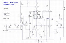
The schematic on the Renardson Audio website has a 100uF connected between Q7 collector and Q5 emitter which I added to the simulated schematic.
I have increased the sine wave voltage source amplitude to 0.317 V to give about 4 V rms at the output which is the level used for the measurement results on the Renardson Audio website.
I also increased the Transient analysis time to 100 ms to allow the circuit to stabilise.
The results are then:-
Total Harmonic Distortion: 0.000185%(0.000910%). I don't understand why there are 2 results. Perhaps the first is calculated by summing the harmonics including the effect of phase so there is some cancellation giving a lower result and the second is just summing the amplitudes?
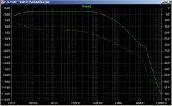
I also used the view FFT waveform arithemtic (right click in the waveform viewer window > View > FFT) on V(vout), number of data points, default, 262144, Use Extent of Simulation Data, Binomial smoothing, default, 3. Windowing Blackman-Harris.
The 2nd harmonic is about -125dB relative to the fundamantal.
I don't know how reliable the results are. The semiconductor models are only approximations, no account has been taken of power supply impedance or any other parasitics.
The error log also has the text .maxstep=0.48831106u Unknown control card.
I think that to have an effect it should be .options maxstep=0.48831106u or be included in the .tran command to set the maximum simulation step size.
I then get a slightly different Total Harmonic Distortion result.
The schematic on the Renardson Audio website has a 100uF connected between Q7 collector and Q5 emitter which I added to the simulated schematic.
I have increased the sine wave voltage source amplitude to 0.317 V to give about 4 V rms at the output which is the level used for the measurement results on the Renardson Audio website.
I also increased the Transient analysis time to 100 ms to allow the circuit to stabilise.
The results are then:-
Total Harmonic Distortion: 0.000185%(0.000910%). I don't understand why there are 2 results. Perhaps the first is calculated by summing the harmonics including the effect of phase so there is some cancellation giving a lower result and the second is just summing the amplitudes?
I also used the view FFT waveform arithemtic (right click in the waveform viewer window > View > FFT) on V(vout), number of data points, default, 262144, Use Extent of Simulation Data, Binomial smoothing, default, 3. Windowing Blackman-Harris.
The 2nd harmonic is about -125dB relative to the fundamantal.
I don't know how reliable the results are. The semiconductor models are only approximations, no account has been taken of power supply impedance or any other parasitics.
Thanks PChi.
I can replicate your results. The one that makes the real difference to the distortion is the use of 100 cycles.
I also amended R12 to 100 Ohms to get Iq = 100mA and R14 to 1K8 to get the "midpoint" at 30V.
I need to learn more about LTSPice to better understand the results!
I can replicate your results. The one that makes the real difference to the distortion is the use of 100 cycles.
I also amended R12 to 100 Ohms to get Iq = 100mA and R14 to 1K8 to get the "midpoint" at 30V.
I need to learn more about LTSPice to better understand the results!
Anywhere on the websites under
Audio Amplifier Design
ARCHIVE
Audio Amplifier Design
was explain in detail, why low THD values don't ensured, that no audible and annoying distortions are present (mainly due too low idle current through the output stage).
Particularly very small needle pulses in the THD-character (fundamental notched out) doesn't change the low THD-value really significant, but sounds very harsh and spicy in an unmusical kind .
Who know the exact URL concerning this explanations from above mentioned websites ?
Thank you very much for an advice.
P.S.: Are there commercial available class AB amplifier devices on the marked, where the approaches from the various MJR-amps are realized ?
Audio Amplifier Design
ARCHIVE
Audio Amplifier Design
was explain in detail, why low THD values don't ensured, that no audible and annoying distortions are present (mainly due too low idle current through the output stage).
Particularly very small needle pulses in the THD-character (fundamental notched out) doesn't change the low THD-value really significant, but sounds very harsh and spicy in an unmusical kind .
Who know the exact URL concerning this explanations from above mentioned websites ?
Thank you very much for an advice.
P.S.: Are there commercial available class AB amplifier devices on the marked, where the approaches from the various MJR-amps are realized ?
Really like this design. Thank you to the folks who got it running in LTspice.
In preparation for an amp build, I've updated the asc file with the tweaks mentioned in the thread.
Unfortunately there is still an issue:
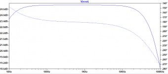
The sim is able to achieve the gain and THD spec'd by MR, but the phase is not linear from 1k-20kHz as shown on his website
I tried simulating MJR7-Mk3 to see if the gain/phase plots would be any different, but they're the same.
Mike, how did your circuit look in simulation?
In preparation for an amp build, I've updated the asc file with the tweaks mentioned in the thread.
Unfortunately there is still an issue:
The sim is able to achieve the gain and THD spec'd by MR, but the phase is not linear from 1k-20kHz as shown on his website
I tried simulating MJR7-Mk3 to see if the gain/phase plots would be any different, but they're the same.
Mike, how did your circuit look in simulation?
Attachments
Hi famiac,
your phase plot looks about right, but you have used a linear scale for the phase and a log scale for frequency. If you used linear scales for both it should agree better with my own plot, being more or less linear, at least from 1kHz to 20kHz. Looking again at my own result the phase scale looks wrong, but I used AIM-Spice which does strange things with the phase, it only plots phase from -180 to +180 degrees, and anything more negative than minus 180 is shown as a positive phase. I need to correct the scale sometime.
Regards, Mike
Haha, what a silly thing to overlook. Thank you Mike.
I see now that by changing the input cap from 2.2u to 47uF i can get a group delay between 3.4-3.2 microseconds from 1kHz to 20kHz.
With a 10uF input cap, the group delay is still between 3.6 and 3.2us
I see now that by changing the input cap from 2.2u to 47uF i can get a group delay between 3.4-3.2 microseconds from 1kHz to 20kHz.
With a 10uF input cap, the group delay is still between 3.6 and 3.2us
Last edited:
Hi, how good are these spice models for the lateral mosfets?
Btw, is the type of model "vdmos"? I ask this because vdmos doesn't work correctly in the simulator I'm more familiar with (microcap).
I'm told that vdmos is now supported in ngspice. The combination of kicad+ngspice might grow into an excellent solution for simulations.
Do the models represent the difference in Cgs of the N and P mosfets, as described by Rod Elliot here? https://sound-au.com/project101.htm
Note that he uses a small cap, value not shown, between gate and source of the N channel to achieve a better match at high frequencies. He mentions stability problems without this cap.
Hi Alexandre,
my own simulations were only linear approximations, using voltage-controlled current sources and so on, using separate capacitors for Cgs and the other mosfet capacitances, using values from the data sheets. I was only interested in stability, and got the information I wanted without needing to trust mosfet models. I did try different gate resistors to compensate for differing Cgs between N and P mosfets when measuring distortion, but found it made very little difference, and the resistors were chosen to protect the gate zeners from excessive current under fault conditions. I don't see why the Rod Elliot circuit would be unstable without the added capacitance, I never encountered that with my own mosfet amplifiers, but he doesn't include component values so it's difficult to even guess what could be the cause, and also there is no mention of the load impedance being used when instability was found.
Regards, Mike
Hi Mike, thank you for the thoughtful reply. This is useful info for builders using laterals, myself included.
Your website is excellent!
Regards, Alex
Your website is excellent!
Regards, Alex
I am still looking for this site and the associated scope-images.Anywhere on the websites under
Audio Amplifier Design
ARCHIVE
Audio Amplifier Design
was explain in detail, why low THD values don't ensured, that no audible and annoying distortions are present (mainly due too low idle current through the output stage).
Particularly very small needle pulses in the THD-character (fundamental notched out) doesn't change the low THD-value really significant, but sounds very harsh and spicy in an unmusical kind .
Who know the exact URL concerning this explanations from above mentioned websites ?
Thank you very much for an advice.
P.S.: Are there commercial available class AB amplifier devices on the marked, where the approaches from the various MJR-amps are realized ?
This topology is one of my favorite circuit designs due an inverted mode, only one voltage gain stage within the feedback loop and speaker DC protect without relay contact in the signal pad.
Maybe this is also a suited circuit to implement a 12-18 db active power filter (active crossover network) without additional active parts such op-amps - basically as described on page 8/15 - 10/15 in the attached file (TDA2030 application) , but as MFB instead Sallen-Key configuration.
Who know URL's to any publications for active filters realize in this kind - i. e. the implementation in present power amplifiers.
Thank you very much
Attachments
Hi tiefbassuebertr
I don't recognise the quote as anything on my website, the nearest thing is on
https://www.renardson-audio.com/test-mk5-dist.html
where I wrote: "At lower levels operation may be limited to class-A, and at higher levels the signal spends a lower proportion of its time in the crossover region, so for this particular amplifier 4V appears to be a good level to check for the effects of crossover distortion." I was suggesting that at higher test signal levels the crossover will be shorter pulses than at medium levels and would measure as lower distortion, but I never investigated further.
Regards, Mike
- Home
- Amplifiers
- Solid State
- MJR7-Mk5 by Renardson