Hi Forr
Most of my listening experience is just hearing my own designs, so I have nothing to compare them with. Also my hearing has detioriorated too much with age, so I am grateful for listening impressions from other constructors. For negative comments it would of course be easier to have criticisms of some easily measured feature such as hum or noise, but more general subjective dissatisfaction is difficult, almost anything could be the cause, maybe a faulty component, some design or layout error, or just the personal preferences of the listener.
I have seen the discussion you linked to. I understand only a little French, and the Google translation is often incomprehensible, but I am happy to see some enthusiasm for the design.
regards, Mike
Hi Mike, I did try not to be negative in post #33, although I can see it could be taken that way.
I have built many tens of amps and IMO quite a lot of the sound character comes from the choice of power transformer and its interaction with the rectifier and PS caps. I cannot provide a definitive reason for this, but it could be due to mains bourne noise and the way it is conducted into the the amp's PS. That said, the MJR7 was built with one of my favourite EI core transformers which I usually find gives excellent subjective results.
The other comment I would make about the subjective quality is that the MJR7 had a similar sound signature to Greg Ball's GB150. Both are 2 stage mosfet amps and both provide a clear, detailed but slightly lightweight sound. My ESP P101 sounds more weighty and has more tonal colour (or perhaps is couloured?). Even further (quite a bit further) on that spectrum are the various NAP implementations I have tried, which range from fruity to grubby.
Which of these is "right" is the $64M question. And that's before I lob my KT88 amp into the equation 😕
On the technical side - the design rationale is beyond any criticism from me and the design, as far as I can tell, is genuinely innovative. The layout and implementation also looks spot on. Good job Mike!
Hi Dave S
Thanks for the further comments, I am happy with 'clear and detailed'. It's just another guess, but maybe the lack of 'weight' could have something to do with the low frequency damping, the MJR7 has even a slightly negative output impedance at very low frequencies so maybe amplifiers with less damping will have a different tonal balance, valve amplifiers in particular may have lower damping. I believe some of the Naim designs use a series resistor at the output, which will reduce damping. Usually the effect should be small, but then again maybe some listeners are more sensitive to that sort of thing.
Regards, Mike
Good point!
Actually my system uses an active crossover and the main amp only has to handle >~100Hz. Despite this the main amp does have a marked effect on bass quality (as well as everything else).
Cheers,
Dave
Actually my system uses an active crossover and the main amp only has to handle >~100Hz. Despite this the main amp does have a marked effect on bass quality (as well as everything else).
Cheers,
Dave
An IMPORTANT additon to my #34 post!
The component references of the Eagle sch. file attached to my #34 post are used:
Mike Renardson recommended to add the D11 diode only if the quiscent current can't be set high enough without it. So first try a short circuit instead of D11. If you still need to add this diode, R11 (68R) has to be decreased to 47R and R9 (470R) has to be increased to 560R. With these modifications in place, small heatsinks should be fitted on T4 and T5, especially if the supply voltage is >60V.
The voltage rating of the 4700u output capacitor should be increased to 100V if the supply voltage is higher than 80V. The capacitor diamater on the layout is 30 mm. It is not recommended to use supply voltages higher than 90V.
I decided to recommission my MJR7-Mk5 and have been running it for the last couple of weeks.
I have revised my opinion on the sound quality of this amp. This is a very good amp indeed, with a clear, detailed and direct sound. However unlike my previous thoughts i am now not finding it a bit lean sounding. I don't know if I have changed something since last time I heard it or if I just got used to the sound.
Overall it is comparable to my MyRef FE (built with the latest audiophile BOM), so I think that's a pretty good recommendation!
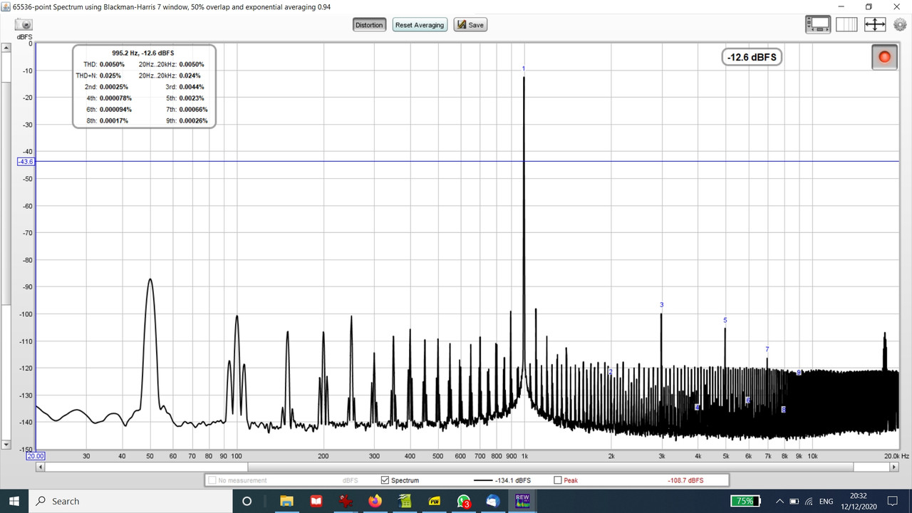
I recently measured the distortion of this amp and it seems like I am not getting anything like the performance that I should be:
I used a very similar layout to the original and used 2SC2240BL & 2SA1085E as the input CFP. The other devices are exactly as per the latest schematic.
The other thing that is strange is that I have never seem the 90 and 110Hz "sidebands" on the 100Hz signal before.
Any ideas what is going on here?
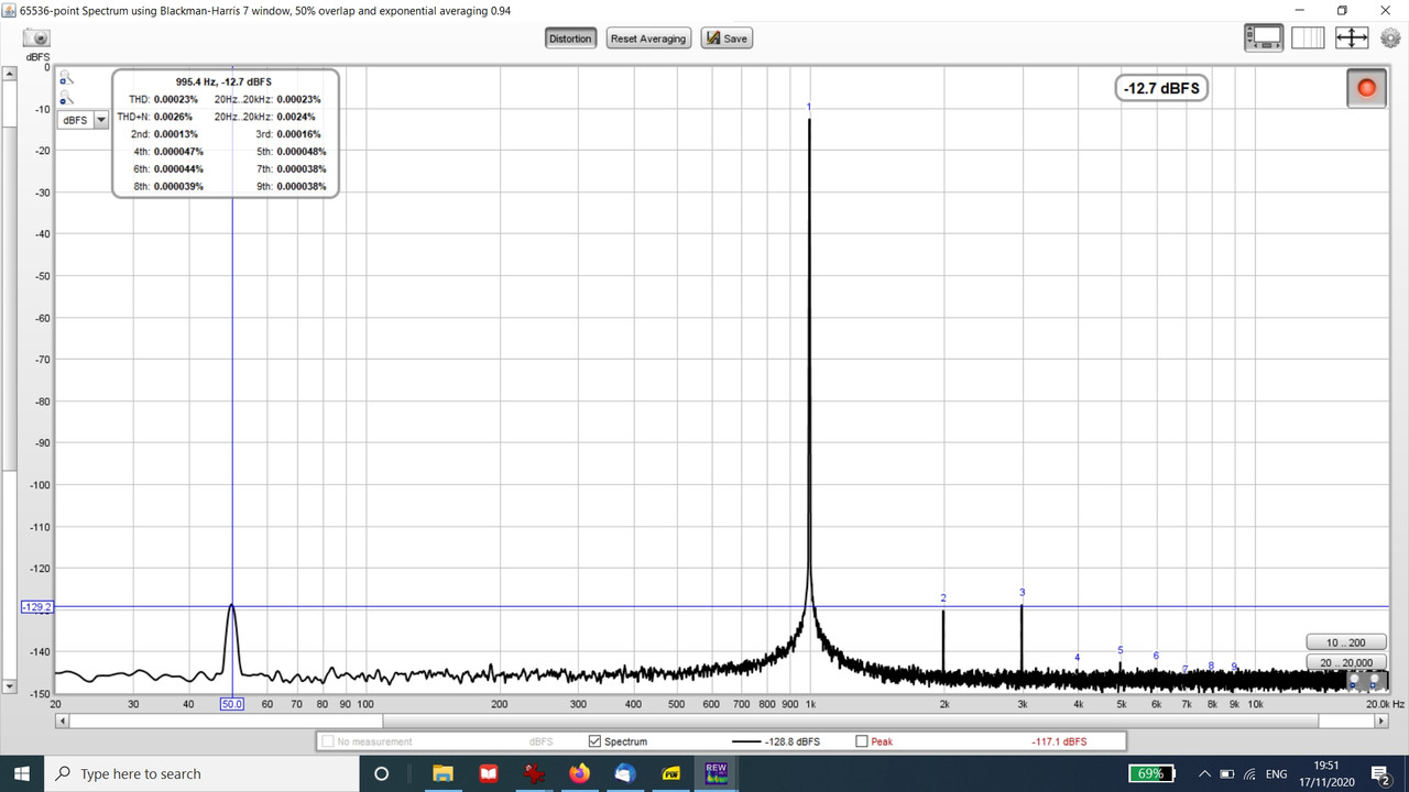
Measurement is by battery powered 1KHz sig gen and ADC is Focusrite 2i2. Baseline performance is:
I used a very similar layout to the original and used 2SC2240BL & 2SA1085E as the input CFP. The other devices are exactly as per the latest schematic.
The other thing that is strange is that I have never seem the 90 and 110Hz "sidebands" on the 100Hz signal before.
Any ideas what is going on here?
Measurement is by battery powered 1KHz sig gen and ADC is Focusrite 2i2. Baseline performance is:
Last edited:
Hi Dave
That doesn't look good. You only specify the output level as -12 dBFS, I assume that is just relative to 'full scale' so I'm not sure what level this is in volts. My first thought is that this looks a lot like being close to clipping. The increase in odd harmonics supports that, the 2nd harmonic is still low. Near clipping the supply breakthrough will also rise so the 100Hz and higher components are to be expected. Those sidebands at +/- 10Hz are less easy to explain, I would guess there is only conditional stability at 10Hz because of the way the output capacitor has been included in the feedback loop, and I actually found a small negative resistance output impedance around 10Hz, so I guess that is being triggered by a fall in loop gain near clipping, but at -120dB that should be nothing to worry about. Did you try reducing signal level a little to see if there was an improvement? Looking at the output on an oscilloscope as the signal level is turned up could be more informative than the frequency spectrum. If this is also happening well below clipping then I have no good idea what could then be the cause.
Regards. Mike
Hi Mike,
Thanks for the reply!
Sorry I should have mentioned that the spectrum was taken at 2.9V RMS into a 10R load (not too far from your tests at 4V).
The reason for the -12.6dB is that this seems to be the sweetspot for noise versus distortion for the 2i2.
However I have realised that my results could be flawed because the sig gen has a 10K pot on the output 😱. So in the worst case the amp is being fed by 5K resistance which will tend to reduce the gain of the amp (inverting mode!).
I think it's more likely to have been fed by <1K ohms - I would need to measure the pot at its test position.
Anyway, I need to buffer the sig gen to do the test properly.
Hi Dave
Thanks for the clarification, at 2.9V the result is far from what I would expect. I assume you have a stereo pair, is it the same on both channels? The signal source impedance shouldn't be a big problem apart from increased interference pickup, but that wouldn't explain the result. Other possibilities include earth loop problems, but again that doesn't entirely explain the spectrum. The increased odd harmonics and 10Hz sidebands only seem to match the onset of clipping, which is impossible at 2.9V, unless the supply voltage is very low. I suggest to check the supply voltage, that the mosfet sources are close to half the supply voltage, and that the quiescent current is at least 100mA. If you don't have an oscilloscope to check for instability maybe try increasing the 100p capacitor to 220p and the 1R5 resistor to 2R2 or 3R3 to see if there is any change. That 2SA1085E could be a problem, I got a few fakes with low current gain the last time I bought some, that could affect stability. The BC560C is also discontinued now, but at least is less likely to be faked. My own tests and those of other constructors have never shown a similar problem, so this is something new and unexpected.
Regards, Mike
Hi Mike,
Supply voltage is 64V. Output is near the middle, I cannot remember exactly but I set in on the 'scope for symmetrical clipping.
I had a quick measure of the pot resistance, I estimate the source impedance to be ~1K Ohms.
The 2SA1085Es were bought from Maplin about 20 years ago (they were specced in the famous Maplin mosfet amp). Measured gain was high, >500 IIRC.
The 2SC2240s were from Toshiba sample stock - I used to work for Tosh.
Both channels have very similar measurements.
I will check again for instability, but didn't find anything suspicious when I originally built the amp a couple of years ago.
If I get chance I will ask my pal to measure the amp on his AP set.
Cheers, Dave
Hi Dave
Thanks for the update, that eliminates the obvious explanations, your idea to get it tested with different test equipment is good if that is possible, maybe that will reveal something different, but for now it's just puzzling.
Regards, Mike
Thanks for the update, that eliminates the obvious explanations, your idea to get it tested with different test equipment is good if that is possible, maybe that will reveal something different, but for now it's just puzzling.
Regards, Mike
My MJR7 is currently with my pal with the AP set. Hopefully he will get round to measuring the amp soon.
In the meantime I am trying to investigate the distortion of the amp using LT spice. However I am also learning LT spice as I go along and due to my inexperience I think I have a problem with getting the operating conditions to converge.
Can anyone help me with the attached file (which does not have all the right transistors yet, as I have modified the Mooly MOSFET amp ASC)?
Attachments
Was the problem failure to find the DC operating point?
LTspice XVII found the operating point for me when I simulated your file. I commented out the option plotwinsize, maxstep, four, and tran Dot commands.
M1 source current = 0.325139 mA.
M2 source current = 19.8367 mA.
It appears that the current is going through R14. Is that correct?
LTspice XVII found the operating point for me when I simulated your file. I commented out the option plotwinsize, maxstep, four, and tran Dot commands.
M1 source current = 0.325139 mA.
M2 source current = 19.8367 mA.
It appears that the current is going through R14. Is that correct?
Thanks for looking at the file.
I just noticed that I had a fatal error in the schematic. This is a single rail amp and I had left dual supplies in place
I think I had also accidentlay selected blue LEDs.
I have now corrected these errors but still cannot get the dc conditions to simulate correctly i.e. the node on the left hand side of C9 (output cap) should be somewhere around 30V, but the sim shows 2V.
I also notice the the cascode transistor Q4 is saturated and all its terminals are at the wrong voltage.
I assume that this is all because the sim needs to charge the output cap before it wil provide the correct results. Problem is... I'm not sure how to do this.
Attachments
It's good to read the that the simulation works for you.
I have changed all the . commands to text by substituting a semi-colon for the . apart from the 'Find DC Operating Point' .op and the .include Cordell Models.txt. I think that the 8m after .op is ignored so I have deleted it. I believe that the DC Operating Point assumes the capacitors to be open circuit.
I get the same result with the node on the left hand side of C9 = 2.04 V.
I think that the problem is that on your schematic there is 100 % DC feedback from the node on the left side of C9 via R18 to the base of Q2. The MJR7-Mk5 schematic on the website shows a 56 kohm connected between the node on the left hand side of 4700u 63 V + terminal (C9 on your schematic) and the 200k feedback resistor (R18 on your schematic) instead of just a wire.
The DC feedback is via a potential divider formed by the 56k and R14 + R25//(R26 + R4). The DC level at the left side of C9 is set by the DC feedback as a multiple of the base emitter voltage of Q2 and the voltage drop across R18.
Yes, brilliant, you have fixed it! Many thanks!
(Can't believe I was dopey enough to miss that resistor out).
I also amended R14 to 3K9 to get ~28V on the "left" side of the output cap.
(Can't believe I was dopey enough to miss that resistor out).
I also amended R14 to 3K9 to get ~28V on the "left" side of the output cap.
That's good news. I have also changed R14 to 3k9 and get 28 V at the left side of the output capacitor.
I think I now have the sim working with the right transistors.
I get a simulated THD of 0.0047% which tallys well with my measured THD of 0.005%.
Both are an order of magnitude away from the results MJR and Forr achieved:
MJR7-Mk5 Test Results
3rd HD is 0.0044% measured by me and <0.0001% in Mike's measurements.
I hope my pal will fire up his AP set soon to shed a bit more light on this quandary.
Attachments
Hi Dave
I never used LTSpice, so happy to see PChi helping with some good advice.
The feedback loop gain should be around 80dB at the 3kHz frequency of the 3rd harmonic, and the open-loop distortion should be around 1%, giving expected closed-loop distortion 0.0001%. Your 0.005% would need either open-loop distortion around 50% or loop gain far under 80dB. I looked at your asc file with a text editor and checked you have the right values for the 1R5 resistor and 100p capacitor, which primarily determine the loop gain, so that looks ok. The only other question is how you set up the 100mA quiescent current in the simulation, that is the only obvious problem I can think of to explain the high distortion. The way I used the 220R preset to set the current could make simulation a little difficult, it needs two resistors adding up to 220R, and adjusting their ratio to set the mosfet currents. Low current will cause rossover distortion which can produce primarily odd harmonics, so that is a possibility.
Also, I have just remembered our earlier discussion, and looking back to post no.39 I said:
'The only big difference to my own layout is including the supply capacitors on the board. There are highly distorted currents flowing through those capacitors and they are close to one of the output inductors which could pick up the magnetic field generated by those currents.' Are you still using the same layout? If so that could be relevant to the high supply breakthrough, and those capacitor currents will include harmonics of the test signal, so there will be some added harmonic distortion. The layout diagram in the previous post no.38 is unavailable now. Other loops could be involved, not just the inductors. I would advise keeping the main supply capacitors further away from the amplifier board, with just a smaller value supply capacitor on the board. I doubt whether this can explain the whole problem, so again double checking the 100mA quiescent current is my advice.
Regards, Mike
- Home
- Amplifiers
- Solid State
- MJR7-Mk5 by Renardson