The wide ranges specified for the mosfet parameters may not be a serious problem in practice, all the recent samples I bought are fairly well matched, with close to 0.6V Vgs at 100mA quiescent current. Of course that could just be luck, but I found a description by Exicon for their lateral mosfets as 'Well matched on Vgs' even though they still use the 0.15 to 1.5V range in their data sheets.
Exicon Lateral MOSFETS - Why use Exicon?
Regarding quiescent current the maximum adjustment is limited by the LED in parallel with the 220R preset, which limits the gate to gate voltage to about 1.7V, which could be too low if the specified maximum Vgs at 100mA was ever needed for both n and p-channel devices, then adding one or two forward biased 1N914 or similar diodes in series with the LED is a solution, but I am not aware of anyone having that problem.
I expected to find lower distortion with higher quiescent current than the recommended 100mA, but found some higher order harmonics increased a little. Using less than 100mA increases open-loop output impedance and may adversely affect stability with reactive loads, so 100mA is both the minimum and recommended level. The exact value is not critical, I usually set my own amplifiers to 120mA total current per channel.
Hi
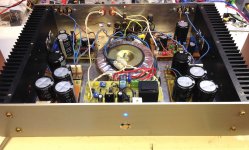
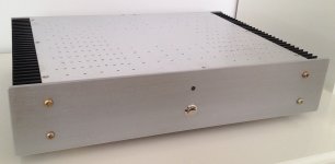
Finaly I finished the power amplifier. It sound realy good. I'm impressed with the sound quality.
Here is some picures off the amplifier and case. It's a 300VA transformer. Supply voltage is 66.6V and the quiescent current is set to 150 mA.
Finaly I finished the power amplifier. It sound realy good. I'm impressed with the sound quality.
Here is some picures off the amplifier and case. It's a 300VA transformer. Supply voltage is 66.6V and the quiescent current is set to 150 mA.
Attachments

Blowing fuses ..........
Hi,
I have a MJR7-MK5 that's always been working fine until today.
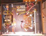
Built exactly as it should ..........
I get 62V DC from my supply, source voltage set to 31V, and quiescent current to 120mA.
The sound is great.
I used to have it working previously with other speakers than the one I'm having now - and these new speakers are needing more current.
Just for the fun, I tried to push the volume very high, and blew the 2A fuse.
Is it ok the have a 2.5A or 3A fuse with this board ? Or not ?
Thanks in advance .......
JMK
Hi,
I have a MJR7-MK5 that's always been working fine until today.
Built exactly as it should ..........
I get 62V DC from my supply, source voltage set to 31V, and quiescent current to 120mA.
The sound is great.
I used to have it working previously with other speakers than the one I'm having now - and these new speakers are needing more current.
Just for the fun, I tried to push the volume very high, and blew the 2A fuse.
Is it ok the have a 2.5A or 3A fuse with this board ? Or not ?
Thanks in advance .......
JMK
Mike Renardson
I have been trying to contact you for nearly 20 years ever since your improved class b amplifier
Please send me a pm
TREV
I have been trying to contact you for nearly 20 years ever since your improved class b amplifier
Please send me a pm
TREV
Hi J.K.M.
The 2A-T fuse was originally specified for an earlier version with a single channel on each board, so the single fuse for two channels on the Mk5 board could be rated for a higher current. I mentioned that somewhere in the design notes. According to some sources T-type anti surge fuses, can typically survive at 10 times their rated current for about 100 msec, and at 5 times the rated current for 1 sec, so a 2A supply line fuse is not necessarily a serious limit to output power. With low impedance speakers driven at continuous high power, then provided the heatsink is not getting too hot , a 3A-T fuse should be ok.
Mike
Hi Mike !
Thanks a lot. I'm going to try a 2.5A-T first and see what happens.
And give you more decent pictures of your baby ........
J-M
PS: and if everything is fine, I intend to change its power supply for a 60V SMPS
Thanks a lot. I'm going to try a 2.5A-T first and see what happens.
And give you more decent pictures of your baby ........
J-M
PS: and if everything is fine, I intend to change its power supply for a 60V SMPS
Last edited:
Board
Hi
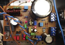
Off course you kan get a pdf. I like this amplifier very much so I am happy if more people builds this small wellsounding amplifier made by Mike Renardson.
Read his komments how you adjust the amplifier. Here is the link Audio Amplifier Design
If someone are interested in the Eagle-file I can post that too.
Livio
Hi
Off course you kan get a pdf. I like this amplifier very much so I am happy if more people builds this small wellsounding amplifier made by Mike Renardson.
Read his komments how you adjust the amplifier. Here is the link Audio Amplifier Design
If someone are interested in the Eagle-file I can post that too.
Livio
Attachments

Hi Livius,
I like your board layout in that it is very compact so perhaps not prone to RF pickup. I'm tempted to build the circuit according to your layout, as soon as I made sure it's not prone to HF instability. Though I have 2 suggestions, but comment on that if I'm wrong.
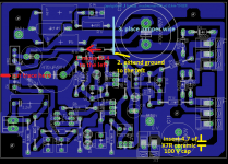
1. The grounding can be made better by a simple modification. In the present layout the return ground current of the output compensation network R17, C14 flows through the input ground. This is generally to be avoided. I would cut the trace at the position shown in the atached image, and insert a jumper wire from a different grounding point.
2. I read about that the supply rail decoupling can be made better in the 100kHz...1MHz range by inserting a 4.7uF X7R ceramic cap parallel to the electrolitic, see atached image, and https://www.neurochrome.com/taming-the-lm3886-chip-amplifier/supply-decoupling/. According to this article the usual 100nF does virtually nothing.
I would try to make these modifications if you provide the Eagle files (although I have to learn using Eagle...).
Another question: did you test the HF stability of your layout? Under capacitive load as well? E.g. 8 Ohm parallel 100nF on output? If you don't have an oscilloscope, you can touch resistor R16 (1 Ohm), if it's hot, then there is HF oscillation. Don't use a real speaker for this test, because the tweeter may be damaged if there is HF oscillation within the amp. Layout can be a contributor to insability even if the theoretical design is mostly OK.
regards
István
I like your board layout in that it is very compact so perhaps not prone to RF pickup. I'm tempted to build the circuit according to your layout, as soon as I made sure it's not prone to HF instability. Though I have 2 suggestions, but comment on that if I'm wrong.
1. The grounding can be made better by a simple modification. In the present layout the return ground current of the output compensation network R17, C14 flows through the input ground. This is generally to be avoided. I would cut the trace at the position shown in the atached image, and insert a jumper wire from a different grounding point.
2. I read about that the supply rail decoupling can be made better in the 100kHz...1MHz range by inserting a 4.7uF X7R ceramic cap parallel to the electrolitic, see atached image, and https://www.neurochrome.com/taming-the-lm3886-chip-amplifier/supply-decoupling/. According to this article the usual 100nF does virtually nothing.
I would try to make these modifications if you provide the Eagle files (although I have to learn using Eagle...).
Another question: did you test the HF stability of your layout? Under capacitive load as well? E.g. 8 Ohm parallel 100nF on output? If you don't have an oscilloscope, you can touch resistor R16 (1 Ohm), if it's hot, then there is HF oscillation. Don't use a real speaker for this test, because the tweeter may be damaged if there is HF oscillation within the amp. Layout can be a contributor to insability even if the theoretical design is mostly OK.
regards
István
Attachments
Hi István
Yes I know. My board is not perfect. 🙁
I have built a amplifier whith this layout and it´s running good.
First I tested a board only whit a resistor load and later whit a speaker. R16 was not hot so I think it´s not oscillating.
I´m interested to see your board when you made the changes. There are always something new to learn.
The attached zip file contains the .brd and .sch files. Contact me if the files not working.
Regards
Livio
Attachments
I was intrigued by the clever and individual design approach of this amp, so I built one. I used a layout very similar to the MR one. Sadly its sound was not quite as good as I expected 🙁
For a similar design but with sound that's more to my taste, I would recommend having a look at the Ion/Nytech circuit.
For a similar design but with sound that's more to my taste, I would recommend having a look at the Ion/Nytech circuit.
Last edited:
Hi Livius and all,
Attached are the Eagle files with some minor corrections.
There was an error in the schematic: pins 1 and 3 of VR1 were shorted. Fortunately this error was not replicated in the board layout. I corrected this in the sch. and also mirrored VR1 vertically in the layout, it should now increase the bias current CW (not CCW as it was).
As Mike Renardson suggested, I also included a diode serial to the D6 LED, just in case the VGS's of the MOSFETs are higher than usual.
Also included is a 4.7uF MLCC capacitor between VCC and GND (it's not important, can be omitted).
Grounding was made a bit different, now the grouding current of the output filter doesn't flow through the input ground point.
I hope I didn't make any new error and it works fine.
István
Attachments
It may mean that you have a preference for more crossover and overall distortion.I was intrigued by the clever and individual design approach of this amp, so I built one. I used a layout very similar to the MR one. Sadly its sound was not quite as good as I expected 🙁
For a similar design but with sound that's more to my taste, I would recommend having a look at the Ion/Nytech circuit.
That is entirely possible. However I am quite pleased with my My-ref FE build and that is a very low distortion amp, so I think there's more to it than just distortion.
I took a quick look at the the My-ref FE design, and that appears to be non-inverting, which may be relevant. The first time I listened to one of my MJR7 mosfet amplifiers, my first impression was that something was wrong. I was playing a track I was familiar with and had heard many times through my previous amplifier, another low distortion mosfet design, and something was definitely different. Then I remembered that the previous amplifier was non-inverting, and the MJR7 is inverting. Adding a switchable inverting stage confirmed that this was causing most of the difference. Another listener confirmed a difference, but we disagreed about which sounded better, and it may just be that I had become accustomed to the older amplifier. Just reversing the speaker plugs easily avoids the inversion, so that at least can be eliminated as a difference. That is one possible explanation for an audible difference, but there are plenty more, including differences in output level, frequency response, output impedance, stability into reactive loads, interference pickup, earth loops, and so on, so I agree there may be more to it than just distortion.
My MJR7 was built with the speaker terminals reversed in case I forgot about the inverting gain, so that's not the reason for any difference.
An externally hosted image should be here but it was not working when we last tested it.
An externally hosted image should be here but it was not working when we last tested it.
Ok then, the inversion was not the problem, that was just a guess. Looking at the layout I don't see anything obviously wrong, the only big difference to my own layout is including the supply capacitors on the board. There are highly distorted currents flowing through those capacitors and they are close to one of the output inductors which could pick up the magnetic field generated by those currents. Again I am just guessing, it's probably only a very small effect. I have no other ideas what the problem could be. I have heard plenty of positive opinions of the design, but maybe it is just a matter of personal preference.
Hi Mike,
Nice to see here. Do you know that there is a quite successful thread about your MRJ7 amp on one of the more active french DIY forums :
MJR7-Mk5 Renardson - 30050751 - sur le forum Amplis et Préamplis - 1056 - du site Homecinema-fr.com ?
Concerning differences when listening amps, I found that a few give an apparently more detailed sound. Those I can name are : TDA2030 1980 Linsley-Hood with MJ2501-MJ3001 at the output; 60 W Crimson circa 1980.
(I once listened to a Nytech and I would be happy to own one), all quite old in fact.
However I noticed the detailed sound of theses amps shows off only at the begining of listening sessions and that I soon forget it.
When listening to Self's blameless or MRJ7, there is not the kind of magic of the previous amps at the begining of listening sessions, but they never lack of details.
I have been a bit puzled by these "magic" amps since long. The only plausible explanation I found was that amps having a bit of distortion and/or noise may sound slightly more attracting precisely because of this bit of distortion and nothing else.
Albeit being passionate by audio circuitry, I am not sure there are great differences of sound between designs.
My active system uses 2 * 3 MRJ7s since 2011.
Regards.
- Home
- Amplifiers
- Solid State
- MJR7-Mk5 by Renardson