Hello to you all. ime new to the diy forum and am looking for advice please
ime in the midle of referbing my mission 770 made in 1981 they are rated at 25-200 watts ive replaced the tweeters and the internal wireing so far and they sound fine as far as i can tell but i think the new tweeters should be brighter than they sound at the moment so was wondering it the caps will need replaceing. They are 33 years old or will they be ok sill as . Any advice would be a big help.
Thnks
Since you're restoring speakers, it would only be logical
to exchange the caps too. A few more quid spent should not be
an issue. You can check the caps with capacitance meter and
see how well the value measured coincides with official marking.
Take the caps out of the circuit for testing.
to exchange the caps too. A few more quid spent should not be
an issue. You can check the caps with capacitance meter and
see how well the value measured coincides with official marking.
Take the caps out of the circuit for testing.
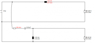
It is good to measure as much as you can, including the DC resistance of the original drivers with a cheap multimeter, and work out how the crossover is wired.
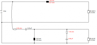
You have probably replaced a 6 ohm 90dB tweeter with an 88dB unit, hence the loss of brightness. You can fix that by changing the value of a resistor in the tweeter filter or even shorting it out altogether. Here, changing a 3.9R to a 2.2R would be a good start. It won't affect impedance badly.
A more advanced alternative would be to increase the value of the bass coil by 50% to take down the level on the bassmid.
You can buy a 40W soldering iron and some 3-10W wirewound resistors at Maplin.
An externally hosted image should be here but it was not working when we last tested it.
You have probably replaced a 6 ohm 90dB tweeter with an 88dB unit, hence the loss of brightness. You can fix that by changing the value of a resistor in the tweeter filter or even shorting it out altogether. Here, changing a 3.9R to a 2.2R would be a good start. It won't affect impedance badly.
A more advanced alternative would be to increase the value of the bass coil by 50% to take down the level on the bassmid.
You can buy a 40W soldering iron and some 3-10W wirewound resistors at Maplin.
Attachments
thanks
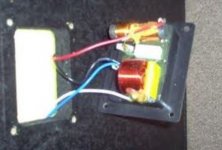
i wondered if it would be a good idea i found a picture of the crossovers on the net they look pretty simple to work on should i also replace the long black things to ?
i wondered if it would be a good idea i found a picture of the crossovers on the net they look pretty simple to work on should i also replace the long black things to ?
Attachments
It is good to measure as much as you can, including the DC resistance of the original drivers with a cheap multimeter, and work out how the crossover is wired.
i must have been writing when you posted your reply. thank you so there resister. at least i know what I'm looking at now thanks again i will have a look
An externally hosted image should be here but it was not working when we last tested it.
You have probably replaced a 6 ohm 90dB tweeter with an 88dB unit, hence the loss of brightness. You can fix that by changing the value of a resistor in the tweeter filter or even shorting it out altogether. Here, changing a 3.9R to a 2.2R would be a good start. It won't affect impedance badly.
A more advanced alternative would be to increase the value of the bass coil by 50% to take down the level on the bassmid.
You can buy a 40W soldering iron and some 3-10W wirewound resistors at Maplin.
S'funny how 90% of two ways use the same simple filter! 
It can be improved too. I usually try a 7.5R/0.68uF Zobel on a 6 ohm tweeter. Improves the top end for smoothness.
Or 8.2R since it's available:
Wirewound 7 Watt 8.2 Ohm Resistor | Maplin
LCR Audio-Grade Polypropylene Axial 630V 680nF Capacitor | Maplin
I don't think much of the coil alignment there. They should be at right angles:
Placement of coils in crossover networks
Looks like an MKT polyester film type capacitor. That won't be improved much by replacement by polypropylene.
Attachments
Last edited:
S'funny how 90% of two ways use the same simple filter!
It can be improved too. I usually try a 7.5R/0.68uF Zobel on a 6 ohm tweeter. Improves the top end for smoothness.
Or 8.2R since it's available:
Wirewound 7 Watt 8.2 Ohm Resistor | Maplin
LCR Audio-Grade Polypropylene Axial 630V 680nF Capacitor | Maplin
I don't think much of the coil alignment there. They should be at right angles:
Placement of coils in crossover networks
Looks like an MKT polyester film type capacitor. That won't be improved much by replacement by polypropylene.
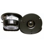
thanks that's loads of info here is a picture of the tweeters ive put in they morel cat 308 - 8 ohm
Attachments
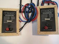
I'm surprised you're struggling for level on the tweeter! Take the fuse out, clean it and put it back.
I've used the Morel CAT 298 which is the simpler version of the 308. It's fairly conventional, so the current crossover will probably be OK. I'd do something more interesting though. Most of us here would!
Do try the Zobel. I find it helps the Morel soft dome tweeters. They are quite bright. I put some insulating tape on the magnet, because the morel input pins and connectors get uncomfortably close to shorting on the magnet on mine.
I've used the Morel CAT 298 which is the simpler version of the 308. It's fairly conventional, so the current crossover will probably be OK. I'd do something more interesting though. Most of us here would!
An externally hosted image should be here but it was not working when we last tested it.
Do try the Zobel. I find it helps the Morel soft dome tweeters. They are quite bright. I put some insulating tape on the magnet, because the morel input pins and connectors get uncomfortably close to shorting on the magnet on mine.
Last edited:
thanks
they are clear just not as bight as i expected. i will look at the fuse maybe they need to be replaced i looked at having them sorted but just for the internal wire and crossover sorted they want loads of money so i decided to do it my self but ive got so far then it came to the crossovers that look simple but it seems there is a lot more to it than just changing parts for new i will have a look and see if i can get some fuses and post what happens. thanks Steve you've been a great help
they are clear just not as bight as i expected. i will look at the fuse maybe they need to be replaced i looked at having them sorted but just for the internal wire and crossover sorted they want loads of money so i decided to do it my self but ive got so far then it came to the crossovers that look simple but it seems there is a lot more to it than just changing parts for new i will have a look and see if i can get some fuses and post what happens. thanks Steve you've been a great help
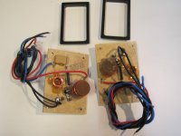
That filter is not the most sophisticated thing, and lacks energy and phase alignment around 5kHz IMO. Which is the area where you get the real dynamics of snare drum and such.
Most of us would lose the fuse altogether, but not hammer it at parties, of course.
While you're at it, check you have the drivers in correct polarity. Your circuit is usually both drivers in positive polarity. Otherwise you get a phasey hole in response at the crossover point.
I was just looking at MKT polyester capacitors again, and they do seem to have a poor dissipation factor around 10%, so a polypropylene might be better.
Building tip. Zip ties and those sticky mounting blocks work well IMO. Less messy than hot glue and epoxy glues.
This is a much better 2nd/3rd order filter. We can look at that when you grow strong in the force that is DIY! It really sounds good.
Most of us would lose the fuse altogether, but not hammer it at parties, of course.
While you're at it, check you have the drivers in correct polarity. Your circuit is usually both drivers in positive polarity. Otherwise you get a phasey hole in response at the crossover point.
I was just looking at MKT polyester capacitors again, and they do seem to have a poor dissipation factor around 10%, so a polypropylene might be better.
Building tip. Zip ties and those sticky mounting blocks work well IMO. Less messy than hot glue and epoxy glues.
An externally hosted image should be here but it was not working when we last tested it.
This is a much better 2nd/3rd order filter. We can look at that when you grow strong in the force that is DIY! It really sounds good.
Last edited:
That looks a little to much at the moment but i will have a go at gettong rid of the fuse is it a simple job? Do i just bridge it i can get to see what value the caps are at the same time. Will it make much difrence takeing the fuses out do you think
It's getting rid of a couple of rusty or oxidised metal contacts for one thing. It's also losing 0.5 ohms fuse resistance IIRC. So it's louder.
15 or 30A fuse wire makes ideal hook up wire for bridging connections. Fuse wire is actually tinned copper, so is really as good as it gets.
Crimped connections to speaker tags get worse with time too, due to oxidation. But you'd need a crimping tool to redo them. Small baby steps needed here at first, as you say.
My pleasure. You have a nice speaker there IMO. It will sound very good in the end, and repay some DIY work.
Troels Gravesen is one of our heroes and inspirations. He rarely puts a foot wrong:
CA18RLY/22TAF-G
Troels Gravesen is one of our heroes and inspirations. He rarely puts a foot wrong:
CA18RLY/22TAF-G
Had a look at my fuses they were dodgy must hve been cheep ones cus the sprin inside the holder has caved all the end of the fuse in an made it loos . Ive put new ones in and they do sound a lot better so it looks like they do have a bit of an impact on the sound.
It dose look like it will be a good idia to bypass them i will do it soon as i have time and take some pics. Thank for all the help
It dose look like it will be a good idia to bypass them i will do it soon as i have time and take some pics. Thank for all the help
I always chat with electrical engineers, like intruder alarm installers, when I meet them. They can tell you a lot about tools and crimping connectors and soldering for instance.
Fuses are more complex than you might think. Sprung types or the ones with a blob of solder in the middle are slow blow IIRC. Straight wire types are quick blow. You usually use slow blow in speakers, since the tweeter takes quite a long time to get damaged by the heat of overpower conditions, and you don't want the fuse to blow with a very momentary condition.
A good engineer always has a good toolkit, lots of spares and measuring devices like a really versatile inductance and capacitance multimeter which starts around £70. Honestly it takes years to accumulate all the stuff you need for a proper job. Here's some of my components below which get recycled quite a lot as designs evolve.
Read the Wilmslow Audio website to get some ideas:
Bits & Pieces
Anyone who says they know it all is lying. But the main thing is to know where you are heading.
Attachments
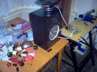
Hello again
been away for a while but have sorted my missions got some good quality fuses in the crossovers and new foundation stands i put ebony cones in between stands and speaker an re bult my speaker cable with new qed spades and bannana plugs they sound loads better thanks for all the help ime hopeing to do more soon but for now they sound great.
Thanks
martin
- Status
- This old topic is closed. If you want to reopen this topic, contact a moderator using the "Report Post" button.
- Home
- Loudspeakers
- Multi-Way
- mission 770 crossover