Hi.
I'm exploring the choice of Inductors for a crossover build.
It's a 3 way Loudspeaker design needing 0.18mH, 0.39mH, 0.56mH, & 1.5mH Inductors in each box.
To keep the build cost down is 20 AWG acceptable, or will it compromise sound reproduction compared to 18 AWG?
A cost comparison from a couple of local suppliers:
All Inductors 18AWG (+ - 3% Jantzen) = AUD$141 vs
All Inductors 18AWG but the 1.5 mH Inductor is 20AWG (200watts + - 5% Dai Ichi) = AUD$96
Speakers are 12" Woofer, Horn Midrange, & Tweeter.
6 ohm Impedance.
100 W RMS DIN.
95Db.
Crossover frequencies:
Woofer to Midrange 1.2 kHz to 2 kHz
Midrange to Tweeter 5 kHz to 10 kHz
cheers
Cliff
Last edited:
I'm assuming you are talking air core here? Hmmm 20AWG is going to be around 1 ohm DCR for the 1.5 mH which is a lot to be putting in series with your woofer.
Even a 18AWG is going to be around 0.64 ohns which is higher than I'd be wanting to use. 15AWG drops to around 0.37 ohms (but you are looking at around $65 for two of those)...
Laminated core coils would be the way to go if you need that size and don't want to spend too much. Wagner has Dayton ones, 1.5mH 0.24 Ohms DCR for $9.50. IC181-5 Inductor Crossover Solid Core - Dayton, Inductors | Wagner Online Electronic Stores
BTW where are you getting your coils from? I put 2 off of each of your coil values into the cart at speakerbug and it only came to $70 (they are jantzen coils). Air-Core
Tony.
Attachments
Last edited:
Hi Cliff!
Further increasing your knowledge of crossovers I see! 😉
What wintermute is saying is that the type of inductor you choose depends on its position within the crossover circuit.
A high value inductor in series with a woofer may need a laminated core in order to reduce the length of wire used in its construction and hence reduce its resistance.
It may be helpful if you attach the crossover schematic.
Last edited:
You can use thinner higher gauge inductors on the small uH values as there is less wire and less resistance. I would aim for the resistance of the inductor to be 5% or a bit less than the resistance of its' load or the impedance of the inductor at the low frequency limit of the inductors' use.
At 1.5 mH I would still stick to air core, as I suspect you are using good drivers also.
I did have an issue once with inductors on a core not really handling their power rating. That can damage amplifiers in addition to sounding awful.
At 1.5 mH I would still stick to air core, as I suspect you are using good drivers also.
I did have an issue once with inductors on a core not really handling their power rating. That can damage amplifiers in addition to sounding awful.
Last edited:
There shouldn't be much of an issue with a 1.5mH ferrite coil like this one: https://cpc.farnell.com/visaton/3601/inductor-x-over-1-5mh-13-4a/dp/FT01393
It uses wire of diameter 1.32mm (18 AWG is around 1mm in diameter), the saturation current is 13.4A and the resistance is 0.17 ohm.
Pricey at £18.40 though, and possibly overkill for Cliff's project!
May we have details of the drivers, along with the crossover schematic, so we can judge the quality of the inductors required, Cliff?
Hi Everyone. Thanks for the assistance.
It's the Technics SB E100's.
The brief is to improve their sound quality without devaluing them by altering their originality.
My proposal is to leave the existing wiring, terminals, and crossover arrangement in place and build a replacement which would run alongside of it.
The new arrangement would have its own binding post, wiring, and crossover and could easily be removed if the owner needed to restore to original.
The rear control panel has a vent area through which the binding post wires could be fed into the Loudspeaker without the need to drill holes.
I'm wanting to maintain the existing manufacturers specifications.
Parts list is:
C1 2.2 µF
C2 47 µF
C3 6.8 µF
C4 6.8 µF
C5 22 µF
L1 0.18 mH
L2 0.39 mH
L3 0.56 mH
L4 1.5mH
I've added the service manual wiring diagram (see attached).
I can't find any information on acoustic characteristics of the drivers other than the Woofer is 30cm is 95Db 1 metre and can handle 100watss continuous, and Midrange and Tweeter drivers are Horn type.
I was hoping to:
a. Select suitable Inductors which will improve the sound reproduction, be electrically suitable, but no break the bank.
b. Create a new wiring diagram with color coded wiring, which a non technical person to follow.
c. Decide on a suitable crossover circuit board which would compliment these speakers.
Hope this isn't a tall order request.
Would love your ideas and input.
Cheers
Cliff 🙂
Attachments
Last edited:
I wound my own in that same value for a project cloning a set of JBL 4406 crossovers a while back, used 18awg on a round plastic spool. They sound great with an 80w amp.
It may be useful to refer to Cliff's previous thread on the Technics SB E100: Loudspeakers, no sound from left Midrange?
Do you intend to incorporate new L pads and breakers into your upgraded crossover, Cliff?
Would you supply photographs of the existing crossover components so we can judge their quality?
And, yes, I would consider your request a big ask! 😀
Do you intend to incorporate new L pads and breakers into your upgraded crossover, Cliff?
Would you supply photographs of the existing crossover components so we can judge their quality?
And, yes, I would consider your request a big ask! 😀
Here's useful information on the different types of inductor, and on how to wind your own inductors. 😎A good way to save money.
How to Use Loudspeaker Crossover Inductors in DIY
Article, How to build a loudspeaker crossover inductor
OK. That brings up more questions. What type of inductors does the original have? Are they ferite or steel cored?
As inductors don't degrade like capacitors, getting better quality by upgrading them, is probably only possible if changing from say cored inductors to air cored inductors. I'm not going to go into whether a foil inductor will be better than a wire inductor, as it is not something that I have any experience with....
If you want them to be as faithful to the original as possible, then you absolutely need to check the DCR of the originals, and try and match that with the new coils. If you don't it may affect the crossover in subtle or not so subtle ways.
As Galu said it is a big ask 😀
IMO the only area you can probably improve by changing out coils, without changing the transfer functions of the crossover, would be with lower distortion (if original coils are cored and being pushed into saturation) and possibly layout (if the original layout of the coils was bad causing cross coupling)...
edit: Oh and on the topic of winding your own coils, you might want to look at my blog posts 🙂
Rolling Your Own (an adventure in coil winding) part I - diyAudio
rolling your own (an adventure in coil winding) part II - diyAudio
Tony.
Last edited:

^ 😀
I guess the other area where you could get improvements (depending on the tolerances of the originals) is with better matching channel to channel of the components, which may help with imaging.
Tony.
I guess the other area where you could get improvements (depending on the tolerances of the originals) is with better matching channel to channel of the components, which may help with imaging.
Tony.
Sorry G. 😱
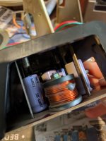
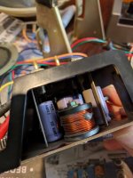
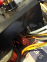
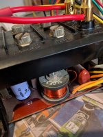
Here are some snaps. The existing network uses substantial parts. The Inductors look pretty good, but have a screw/bolt arrangement down their cores. The caps are mostly very old electrolytic.
There is one brown old style poly cap similar to Shizuki
Difficult to read but I think it's marked 22 5 K 100 V.
The existing circuit board isn't suitable to use as it's sandwhiched together between it and the control panel leaving little room to fit anything.
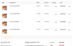
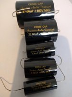
The owner just arrived with a set of Jantzen Cross Cap replacement caps as listed earlier.
Hope this helps.
Here are some snaps. The existing network uses substantial parts. The Inductors look pretty good, but have a screw/bolt arrangement down their cores. The caps are mostly very old electrolytic.
There is one brown old style poly cap similar to Shizuki
Difficult to read but I think it's marked 22 5 K 100 V.
The existing circuit board isn't suitable to use as it's sandwhiched together between it and the control panel leaving little room to fit anything.
The owner just arrived with a set of Jantzen Cross Cap replacement caps as listed earlier.
Hope this helps.
Attachments
Hmmm that could get even more tricky. Is the bolt making the coils the value on the schematic, or is it something they did not think about and is actually changing the value completely!
The original design may have been compromised because of a manufacturing decision, but it could also be that that bolt was factored into the values...
Tony.
The original design may have been compromised because of a manufacturing decision, but it could also be that that bolt was factored into the values...
Tony.
Not really more difficult as you have multiamp connector input, it'll be easier to make some new boards into an external box than to adapt to the existing board.
You'll need to measure inductors so dismantle the pcb from case though.
Edit: Wintermute, if Cliff measure them in place ( with leads disconected from circuit) wouldn't he have correct readings?
You'll need to measure inductors so dismantle the pcb from case though.
Edit: Wintermute, if Cliff measure them in place ( with leads disconected from circuit) wouldn't he have correct readings?
Last edited:
OK. That brings up more questions. What type of inductors does the original have? Are they ferite or steel cored?
As inductors don't degrade like capacitors, getting better quality by upgrading them, is probably only possible if changing from say cored inductors to air cored inductors. I'm not going to go into whether a foil inductor will be better than a wire inductor, as it is not something that I have any experience with....
If you want them to be as faithful to the original as possible, then you absolutely need to check the DCR of the originals, and try and match that with the new coils. If you don't it may affect the crossover in subtle or not so subtle ways.
As Galu said it is a big ask 😀
IMO the only area you can probably improve by changing out coils, without changing the transfer functions of the crossover, would be with lower distortion (if original coils are cored and being pushed into saturation) and possibly layout (if the original layout of the coils was bad causing cross coupling)...
Tony.
Hi Tony
From what I can tell the originals are air core wound on bobbins with a bolt through each to secure them to the circuit board.
The Inductors have part numbers but I was unable to get any information on the net regarding their specs other than the values in mH. So I'm at sea regarding their DCR. I was hoping to atleast maintain the performance as a minimum and improve in the cap area, but if Inductor improvement can be gained, that's a bonus.
The existing Inductors are spaced approx 3 cm apart from each other but are all parallel to each other and their magnetic fields are possibly interfering with each other. I understand coils should be placed at 90 degrees to each other to reduce interference. I also don't like the way they were fastened to the circuit board. The bolt passing through the core might act as an iron core in some fashion. Much better synthetic ties.
The improvement I was hoping would be from the Cap replacement.
Parallel circuit board is only being considered due to the lack of real estate in the existing one as well is the need for originality.
But you do raise an important point.
Will this project realize a sound improvement?
Last edited:
Hmmm that could get even more tricky. Is the bolt making the coils the value on the schematic, or is it something they did not think about and is actually changing the value completely!
The original design may have been compromised because of a manufacturing decision, but it could also be that that bolt was factored into the values...
Tony.
This would be a shame.
Taking apart the existing circuit board involves extensive work and de soldering of many parts.
You raise in interesting point.
"Is the bolt making the coils the value on the schematic, or is it something they did not think about and is actually changing the value completely!"
Judging by the orientation of the coils (all sitting upright) I'd say they never thought about it.
- Home
- Design & Build
- Parts
- Minimum acceptable AWG for Inductors on Crossover build?