Guys... hê-hê... again today I sat down and stared at the tangle of wires and remembered something I read about Darlington step being good for high gain and drive...
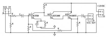
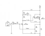
I tried it! I made a Darlington pair with the 3055 at the final and a MJE4919 - input drive is done by a BC560.
Sound is fairly neutral and gain is massive! Had some oscillation issues but sorted that with a cap and resistor here and there.
D
I tried it! I made a Darlington pair with the 3055 at the final and a MJE4919 - input drive is done by a BC560.
Sound is fairly neutral and gain is massive! Had some oscillation issues but sorted that with a cap and resistor here and there.
D
Let me put down another few points:
Objective of this project? An extremely simple SE amplifier using solid-state devices (much like them 300B amps), low output but a bit of gain, something novel but enjoyable.
Okay?
D
Objective of this project? An extremely simple SE amplifier using solid-state devices (much like them 300B amps), low output but a bit of gain, something novel but enjoyable.
Okay?
D
GlidingDutchman said:
An extremely simple SE amplifier using solid-state devices (much like them 300B amps), low output but a bit of gain, something novel but enjoyable.
Okay?
D
Western Electric should sue you for libel as well.
Isn't a basic electronics text worth reading prior to D Self?
adason said:just built this and you will be happy with it
http://redcircuits.com/Page80.htm
All fine and well but I would like to start from scratch as I have already done... its much more exciting!
D
analog_sa said:
Western Electric should sue you for libel as well.
Isn't a basic electronics text worth reading prior to D Self?
Okay - this time I will laugh!! Ha-ha! There you go...
Uhm... what about the text goodies? I am blind in this electronics world you know... ???
D
GlidingDutchman said:
Okay - this time I will laugh!! Ha-ha! There you go...
Uhm... what about the text goodies?
I am blind in this electronics world you know... ???
We all have to learn from start --- when comes to new things, like design with transistors & whatever.
Even once Nelson Pass was a 'newbie', a learner.
Now, if anyone want to learn, some what is there to learn and see
about TurnTables and Super Vinyl reproductions:
😎 Go visit GlidingDutchman website, Pleeease!
It is simply one of the best turntable sites I have ever seen on the web 🙂
Lot's of intresting Images of state-of-the-art Phono DIY homebuilt constructions.
Very good & a visit recommended to any Really Audio interested.
http://www.theanalogdept.com/
Lineup 🙂 best greetings to GlidingDutchman & thanks for your website
----------------------
One Example: Good Azimuth alignment

lineup said:
Now, if anyone want to learn, some what is there to learn and see
about TurnTables and Super Vinyl reproductions:
😎 Go visit GlidingDutchman website, Pleeease!
It is simply one of the best turntable sites I have ever seen on the web 🙂
Lot's of intresting Images of state-of-the-art Phono DIY homebuilt constructions.
Very good & a visit recommended to any Really Audio interested.
http://www.theanalogdept.com/
Lineup 🙂 best greetings to GlidingDutchman & thanks for your website
----------------------
Uhmm - much obliged... yup, that is me!
An externally hosted image should be here but it was not working when we last tested it.
and my system (more or less)
An externally hosted image should be here but it was not working when we last tested it.
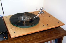
My latest turntable - the DEWAUDIO Credence - see attachment
D
Attachments
Dank u voor uw bijdrage - ik waardeer het werkelijk. Nu kunnen wij deze ontwerpen bespreken!
Thank you Tschrama!
I am glad you see the design goal here and contribute by supplimenting the circuits.
Last night whilst testing I noticed the circuit picks up AM broadcasts... is this natural? How can it be damped?
D
Thank you Tschrama!
I am glad you see the design goal here and contribute by supplimenting the circuits.
Last night whilst testing I noticed the circuit picks up AM broadcasts... is this natural? How can it be damped?
D
Hi,
Putting a fixed current sink on the output is still single ended.
Take a look at some amplifier circuits and note the small capacitor
values around the input. Nearly always for radio rejection.
🙂/sreten.
Putting a fixed current sink on the output is still single ended.
Take a look at some amplifier circuits and note the small capacitor
values around the input. Nearly always for radio rejection.
🙂/sreten.
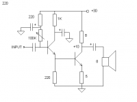
tschrama said:3rd .. now with bootstrapping.. gives a nice steady declining THD spectrum.. 0.3% at 2.5Vrms output.
cheers..
This scheme works the best! Very good overall response and good drive. Noise is very low and so is the destortions.
I would like to build a neat little headphone amp with it. Any others game?
D
GlidingDutchman said:
This scheme works the best! Very good overall response and good drive. Noise is very low and so is the destortions.
I would like to build a neat little headphone amp with it. Any others game?
tschrama .. is a good designer.
He has experience needed, to build simple & good.
(Most anybody can do complicated & advanced amplifiers that are 'good'.
It takes a true Amplifier/Transistor understanding, to keep it very simple & still good)
Gliding, hope Holland will do well against Frankreich, tonight. Holland 'crushed' the Italy with 3-0. Super! My own Sweden will have a hard time with Spain. Tomorrow.
I will see, if I can dig up some old and simple stuff.
I remember an old thread, about Very Simple 2 stage designs.
Even Nelson posted his variant 😎
Regars, Lineup
--------
edit:
Think it was this topic from 2002, by a netherlaender!
Simplest amplifier possible with BJT's
And This was Nelson Pass first suggestion:
http://www.diyaudio.com/forums/showthread.php?postid=51917#post51917
HIS CIRCUIT schematic, see my attachment
Attachments
Indeed , that is a very nice old little thread with contributions of Lars and Nelson...plenty of links to minimalist circuits..
.....What??? no Football icon??
.....What??? no Football icon??
hi.
there are 3 connections to any amplifier
1. Source. signal input
2. Supply. power energy input
3. Load. Signal output to Load
We can say 'an amplifier' is an adapter between input Source & Load.
An adapter that will amplify input signal and adjust it to Load requirements.
CD-player output ->>> Speakers 8 Ohm
wont work, you know
When setting up an amplifer, we need good info about those 3.
Source.
Cd-players, normally, would want at least 10 kOhm - 22 kOhm load to work into.
( 8 Ohm or 55 Ohm, AKG K 240 MK II, will need too much current for CD output )
This is why we need an adapter. A headphone amplifier.
😎
I think I have what I need.
I be back with my circuit suggestion.
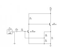
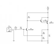
I will use mkax 3T or max 4T design. (max 4 transistors)
🙂 Information of The Three factors. 🙂
1. You will feed from a CD player.
Input impedance, resistor, needs to be like 10-22 kOhm.
2. Power input = 12 Volt DC lead acid battery.
Good if amplifier does not take excessive currents = empty your battery in a few hours 😀
Battery has a good feature. Has got no 50 Hertz hum problems.
It is clean and good power, without a lot of filtering electrolytic Capacitors.
3. Output. LOAD = 2x 55 Ohm AKG headphones.
The sound pressure produced (sensitivity) is:
91 dB SPL per 1 milliWatt,
(or +104 dB/ 1 Volt rms input)
4. Output devices. One or two 2N3055 power transistors.
there are 3 connections to any amplifier
1. Source. signal input
2. Supply. power energy input
3. Load. Signal output to Load
We can say 'an amplifier' is an adapter between input Source & Load.
An adapter that will amplify input signal and adjust it to Load requirements.
CD-player output ->>> Speakers 8 Ohm
wont work, you know
When setting up an amplifer, we need good info about those 3.
Source.
Cd-players, normally, would want at least 10 kOhm - 22 kOhm load to work into.
( 8 Ohm or 55 Ohm, AKG K 240 MK II, will need too much current for CD output )
This is why we need an adapter. A headphone amplifier.
😎
I think I have what I need.
I be back with my circuit suggestion.
I will use mkax 3T or max 4T design. (max 4 transistors)
🙂 Information of The Three factors. 🙂
1. You will feed from a CD player.
Input impedance, resistor, needs to be like 10-22 kOhm.
2. Power input = 12 Volt DC lead acid battery.
Good if amplifier does not take excessive currents = empty your battery in a few hours 😀
Battery has a good feature. Has got no 50 Hertz hum problems.
It is clean and good power, without a lot of filtering electrolytic Capacitors.
3. Output. LOAD = 2x 55 Ohm AKG headphones.
The sound pressure produced (sensitivity) is:
91 dB SPL per 1 milliWatt,
(or +104 dB/ 1 Volt rms input)
4. Output devices. One or two 2N3055 power transistors.
AKG K 240 MK II
http://www.akg.com/site/products/powerslave,id,1063,pid,1063,nodeid,2,_language,EN,view,specs.html
Type semi-open, dynamic headphones
Sensitivity 91 dB/mW, 104 dB/V
Frequency range 15 to 25,000 Hz
Rated impedance 55 ohms
Max. input power 200 mW
An externally hosted image should be here but it was not working when we last tested it.
Hi Lineup
I have the AKG K240 pro edition which is 600 ohm as well as a set of K141 edition also 600 ohm.
They work well on the circuit as adjusted by Tschrama.
I use an EAR 834P phono-stage (12AX7 tubes) for the phono section.
Will probably run the headphone amp from the main amp's tape outputs.
D
PS - Holland's football team's got my support!
GlidingDutchman said:Hi Lineup
I have the AKG K240 pro edition which is 600 ohm as well as a set of K141 edition also 600 ohm.
They work well on the circuit as adjusted by Tschrama.
I use an EAR 834P phono-stage (12AX7 tubes) for the phono section.
Will probably run the headphone amp from the main amp's tape outputs.
PS - Holland's football team's got my support!
How much current drive output max, can mains tape output
or any other source you want to use, e.g. tube preamp output, provide.
Tube preamps, as far as I know, likes a bit higher impedances connected.
Say maybe 100 kOhms.
So, if I am correct in this, then is good if headphone amp should have input impedance 100 kOhm.
Will take most anything: tape out, tube preamp, cd-player.
If your headphones have Load impedance = 600 Ohm,
then we might need at least Voltage Gain ~ x4 - x8.
On the other hand, the good side, 600 Ohm will take/need like 10 times less current!
1 Volt / 600 Ohm = 1.667 mA
1 Volt / 55 Ohm = 18.16 mA
- Status
- Not open for further replies.
- Home
- Amplifiers
- Solid State
- Minima SE Class A amplifier - help please