Bought a new MiniDSP 4x10, will use it for a 2x3-way project.
Before connecting to my amplifier I measured output resistance, to check my new cables.
On all channels, except channel 4, I measure about 10kOhm, on channel 4 the value was >30kOhm.
Same values on RCA outputs.
I contacted support: "All units are QC 5times so I think that your 4x10 is all fine. No worries. 🙂 "
Should I be worried?
Anyone with a 4x10? Can you measure your values?
How did you measure this? Output impedances use to be below 600 Ohms. Input impedances above 10 kOhms.
I measured resistance with a Fluke multimeter for the purpose of checking my new DIY cables.
I'am not interested in output impedance, just checking my cables.
I'am not interested in output impedance, just checking my cables.
But you wrote: " I measured output resistance". Did you measured your cables attached to the miniDSP?
The output resistance is about 560 ohms on all of the miniDSP units. Your measuring scheme is faulty.
Dave.
Dave.
There are no minidsp schematics I have ever seen. Since they use multilayer boards its a PITA to trace them out and sketch up a schematic. However, did manage to trace out some subsystems on two of their boards. Seem likely something like that would be necessary to get to the bottom of why channels measure differently. From the perspective of minidsp the unit is probably fine if it meets or exceeds their published specs.
My 4x10 also shows a higher value of DC resistance on channel 4 (powered on - no input signals) but, while this is interesting, a DC resistance test on the outputs of what I assume are AC coupled outputs is not going to yield useful measurements. Now my curiosity is piqued; it may be that leakage paths on this channel are lower. Hmmm...
You can't just measure output resistance with a DVM. A more involved process is required.
http://www.sengpielaudio.com/calculator-InputOutputImpedance.htm
Dave.
http://www.sengpielaudio.com/calculator-InputOutputImpedance.htm
Dave.
Agreed about measuring output impedance. Easy enough to find out more about it: https://www.google.com/search?q=how...9i57j0i13l9.8895j0j1&sourceid=chrome&ie=UTF-8
Interesting, something with the design then, and nothing special with my unit. Feel better now. 🙂My 4x10 also shows a higher value of DC resistance on channel 4 (powered on - no input signals) but, while this is interesting, a DC resistance test on the outputs of what I assume are AC coupled outputs is not going to yield useful measurements. Now my curiosity is piqued; it may be that leakage paths on this channel are lower. Hmmm...
I'am not interested in the output impedance. Just measured to verify my cables, and surprised that one out of 8 channels has a different design.
Thank you everyone for clarifying!
No, one channel does not have a different design. All eight channels are identical.
If your DVM revealed a different measurement, it's because you had a bleed charge in the output capacitors and/or some other variable.
You CAN'T measure output resistance (reliably) with a DVM. I'm not sure why this concept is seemingly so difficult to accept.
Dave.
If your DVM revealed a different measurement, it's because you had a bleed charge in the output capacitors and/or some other variable.
You CAN'T measure output resistance (reliably) with a DVM. I'm not sure why this concept is seemingly so difficult to accept.
Dave.
Yes, it is the wrong way to go about measuring impedance. I am an electrical engineer in product design and I stand by the evidence that channel 4 output resistance is different from the others, however it is almost certainly inconsequential to the performance of the device. It is merely interesting.No, one channel does not have a different design. All eight channels are identical.
If your DVM revealed a different measurement, it's because you had a bleed charge in the output capacitors and/or some other variable.
As an electrical engineer, you should have the intellectual curiosity to measure this in the proper way.
My goodness.
Dave.
My goodness.
Dave.
Please spare me of your pedantry. It is safe to assume that the in-band impedance is the same for all channels - my focus is on the DC values and why there is a difference, and this is due to intellectual curiosity.As an electrical engineer, you should have the intellectual curiosity to measure this in the proper way.
My goodness.
Dave.
I opened my box and do in fact see that two resistor pairs for channel 4 are 51k (513 code, and as measured with my meter), while all the other channel pairs that are in the same relative positions are 10k 1% (01C code). These are resistors near the balanced output section. Now we know what, but not why.
Attachments
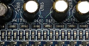
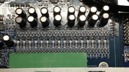
Nice work.I opened my box and do in fact see that two resistor pairs for channel 4 are 51k (513 code, and as measured with my meter), while all the other channel pairs that are in the same relative positions are 10k 1% (01C code). These are resistors near the balanced output section. Now we know what, but not why.
Would be interesting to know why the design of channel 4 is different.
I will out of curiosity send the question to the support ...
I suspect that at some point in the product's development an engineering change order (ECO) was created with the intent of changing the values of all 16 resistors from 51k to 10k, but these two were overlooked.
- Home
- Source & Line
- Digital Line Level
- MiniDSP 4x10