The wattage on R9 ,the 499 ohm resistor is about 90 mW, good for 1/8 watt resistor.

Since the ground plane on the PCB isn't visible, where might the turntable ground be best placed.? Any experience?
Not yet there on the build, just planning the layout.
Not yet there on the build, just planning the layout.
After reading my post I don't think my question was very clear, so let me try again.
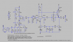
The phono preamp ground, on the PCB, should be connected to chassis along with the turntable ground. My question is where the chassis ground should be connected to the PCB ground. The ground points on the the Mini Pearl PCB are limited because the ground plane is an inner layer.
The convenient ground connections are the input, output, regulator filter capacitors and power ground?
After reading my post I don't think my question was very clear, so let me try again.
The phono preamp ground, on the PCB, should be connected to chassis along with the turntable ground. My question is where the chassis ground should be connected to the PCB ground. The ground points on the the Mini Pearl PCB are limited because the ground plane is an inner layer.
The convenient ground connections are the input, output, regulator filter capacitors and power ground?
Try them all and report back. This is DIY.
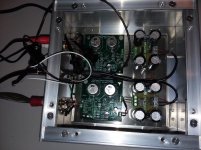
Completed my Mini Pearl SOIC boards. Measurements are with the boards on the bench and power connections made with clip leads.
Soundcard interface loopback
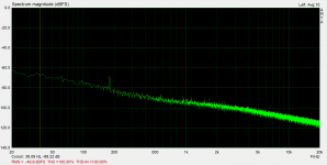
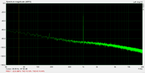
Mini Pearl noise
Mini Pearl 2mV input
The output was 590 mV, so about 49 dB gain
Soundcard interface loopback
Mini Pearl noise
Mini Pearl 2mV input
The output was 590 mV, so about 49 dB gain
Attachments

Made some RIAA measurements and the curve was within 0.15 dB across the audio band, 20 to 20K Hz reference to 1KHz.
Hooked up the turntable and had a listen. Surprisingly very little hum with clip leads and laying out on the work bench, so that is promising for when all is in the enclosure.
BDP
Hooked up the turntable and had a listen. Surprisingly very little hum with clip leads and laying out on the work bench, so that is promising for when all is in the enclosure.
BDP
Attachments

I appear to have ordered a mix of thin and thick film smd resistors and I’ve read the thickies can be not as accurate as the thinnies
Can anyone advise wether I can use thick in and out of the signal path or will this be detrimental to the circuit ?
Can anyone advise wether I can use thick in and out of the signal path or will this be detrimental to the circuit ?
Texas Instruments has announced a new NJFET with gm of 68mS and Idss of 24 to 46mA, and noise in the vicinity of 0.9nV/RtHz.
Boards will have to be reworked as its the unit clamp diodes. No profile is yet available for the dual version. See description here: JFE150 data sheet, product information and support | TI.com
The "dual" version which will make life simple AND it will be available from the usual suspects (DK, Mouser, Arrow etc.)
Since the transconductance is prodigious, only two duals will be needed for gain of 60+ dB.
Attachments
I could have boards made for both versions, but will wait until TI comes out with a profile of the part.
Just a few finishing touches to wrap it up. Testing various points of chassis to signal ground for hum. Doesn't seem to make much difference. Output grounds seem to work.
Sounds great, quiet.
I had a low frequency oscillation initially with one of my preamps when the volume was turned up pretty loud, when disconnecting one of the outputs it would stop. The preamp plays fine with other sources. Another preamp had no issues.
Rewired some of the grounding on the preamps output to more of a star ground instead of bus/star combination and its fine now. Interesting?
Listening to some old albums, Herbie Mann, Dire Straits and Willie Nelson.
Attachments
Installed two 2sk2145 Front end FETs on the SOT mini pearl boards. The 2sk2145s are dual FET GR grade (2.6-6.5ma) in a super mini type package. The installed bias currents were 7ma and 8ma per device with each device sharing a 10 Ohm source resistor. The measured gain for the first stage came out to be 22 or 26.8dB.
Planning on using 2sk209 FETs for the second gain stage.
Planning on using 2sk209 FETs for the second gain stage.
- Home
- Amplifiers
- Pass Labs
- Mini Pearl