Hi,
Great work !
I would be happy if you could send me zipped gerber files. I got others PCB to order soon 😀
Thanks
Damien
Great work !
I would be happy if you could send me zipped gerber files. I got others PCB to order soon 😀
Thanks
Damien
I have sent out most of the boards, will wait to see who doesn't pay to knock them off the list and provide for others.
Yes, I will post the gerbers, or I can send them as a zipped file.
Grazie mille!

Note that in SMT-land we're not dealing with precision caps (resistors are always 1% or better) so to trim the passive RIAA I "tack solder" two pieces of #24 AWG wire onto the pads and play around with the values until I get a reasonably close fit.
The LF is going to fall off more sharply than "flat" -- (and a good thing to!) but you can remedy this if you like by using 1uF coupling cap for the gate of Q4.
The LF is going to fall off more sharply than "flat" -- (and a good thing to!) but you can remedy this if you like by using 1uF coupling cap for the gate of Q4.
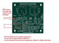
I used the designations from the Lipshitz article, here R100=6.8k or 6.81k and R200 = 909 or 990 ohms. You will note that I have allowed use of 1k||100k as R200a||R200b.
Also -- a 0.100" provision for R20 which can be a through-hole resistor for loading MC carts.
Also -- a 0.100" provision for R20 which can be a through-hole resistor for loading MC carts.
Attachments

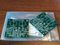
Received a set of SOT23 boards. They are really nice, thank you!
Should we run a mini GB for those SOT23 LSK189 to get those matched?
Should we run a mini GB for those SOT23 LSK189 to get those matched?
I don't know whether the drain and source of the 2SK209 are inter-changeable. SOT23 is, I believe, a slightly smaller profile than Toshiba's TO-236
> I don't know whether the drain and source of the 2SK209 are inter-changeable.
They are. I used them as such everywhere.
Patrick
They are. I used them as such everywhere.
Patrick
Any ideas how many of LSK170B I need to buy to get them matched for the preamp?
The devices Wayne used were "A" variety -- lower IDss
You need 6 devices per board -- the driver stage doesn't have to be that tightly balanced, but the input devices should be close. You have to consider as well that one of the critters might escape.
2SK209BL appears to fit! Idss is high, between 8 - 11mA, transconductance ~15mS. so the GR variety is preferred. Mouser has them in stock.
Shoulda thought of that, I could have matched a whole bunch.
Got a pair of the SOT23 boards, they look great, thanks!
I don't have much experience with surface mount devices, but I'm using this project to learn something.
It sounds like you could use the Toshiba 2SK209-GR instead of the LSK170B component in this design? I'm looking at the 2SK209-GR and it comes in the SC-59 package - is that basically interchangeable with the SOT-23 package?
Do you have any advice about how to go about matching the 2SK209-GR components? I was thinking of following this procedure JFET matching information – diyAudio Store and ordering maybe 30 or so of the 2SK209-GR. Does that sound like a reasonable approach? Thanks!
On matching SOT devices -- solder up the input stage per usual, but do NOT include the 4 JFETs. Power up +24V using a digital ammeter to measure current. Using a pair of insulated tweezers, place the JFETS one at a time on an SOT23 pad and measure the current.
This is somewhat similar to the method Sam Groner used to match BF862's for his LNA described in Volume 3 of Linear Audio.
Or you can buy a 3M SOIC test adapter and use your Peak DCA55 to characterize the devices.
This is somewhat similar to the method Sam Groner used to match BF862's for his LNA described in Volume 3 of Linear Audio.
Or you can buy a 3M SOIC test adapter and use your Peak DCA55 to characterize the devices.

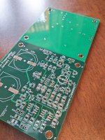
The boards are 4 layer -- signals level on top, V+ layer 2, ground layer 3, V- bottom.
Don't drill any new holes on the board.
Don't drill any new holes on the board.
- Home
- Amplifiers
- Pass Labs
- Mini Pearl