If internal box reflections come back through the cone........I have never seen this on any near field measurement I have made of a woofer or cone midrange driver.
They do if high enough amplitude; can stand out like 'sore thumbs' with many vintage FR drivers.
Ever measured [wide range] woofers in an empty box big enough to generate eigenmodes in the driver's usable pass band?
yes, stuffing tends to "kill the sound".
-though like anything it depends on a number of variables, the most significant being the driver itself.
Basically: keep stuffing away from the driver itself and OFF of the (interior) walls of the cabinet.
Suspending stuffing (centered in-box) can typically provide the objective superiority of a design with stuffing, but still keep the subjective "low-level" detail of an "empty" box.
You need at least 4" of fill to adequately damp freq.s nearing 200 Hz, and note that thick fiber tends to work less well at higher freq.s.. Ultra-touch insulation tends to do these lower freq.s (with 4"+ thick) AND higher freq.s pretty well.
Last edited:
CC's designs have a fair bit of modeling (Comsol) to get better performance (though it is a mid-bass design).
The Arabesque Speaker series by Crystal Cable
Note: it's both an internal and external modeled design.
The Arabesque Speaker series by Crystal Cable
Note: it's both an internal and external modeled design.
.
Too much stuffing kills the sound that's my findings.
+1 'Less is more' 😉
I am one of the people that have featured a complicated internal shape for my enclosures. In all honesty, it was something I had seen once in a translam build. As I was going to do translam anyway, primarily for the outer shape flexibility, I figured it wouldn't hurt to 'play' with the inside shape as well. At the very least it gave me a varying outer wall thickness.

More important, the outside shape does matter in my humble opinion. I envisioned a smooth egg shaped cabinet would have some advantages compared to a more regular box shaped enclosure. I wanted to avoid sharp edges and have the biggest radius I could use, flowing into the sides etc...
At a later date I stumbled upon some pictures of a back mounted driver and as it looked smooth to me I decided to hunt the internet to 'see' if it had any drawbacks. I found some evidence pointing at better behavior than flush mounted drivers(*) with a driver mounted behind a 8 mm baffle with a roundover of the edge. As I really liked the look, it is what I went with at the time.
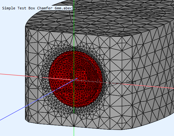
Fast forward to some weeks ago, we were able to test the differences with ABEC. That simulation requires 3D models that are quite detailed and accurate to function well, just look at the ATH Horn thread for many samples.
In collaboration with member fluid, we decided to test the shape I have used in my arrays compared to a flush mounted driver with the same enclosure shape and a more traditional boxed shape (with roundover).
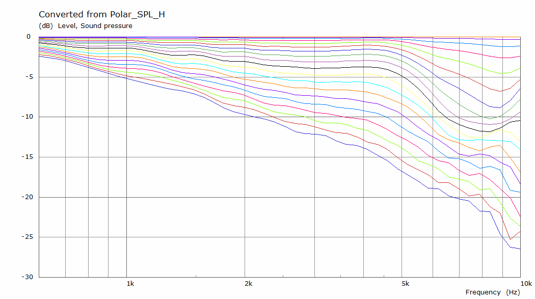
Let's see that story in pictures, starting with the simple box:
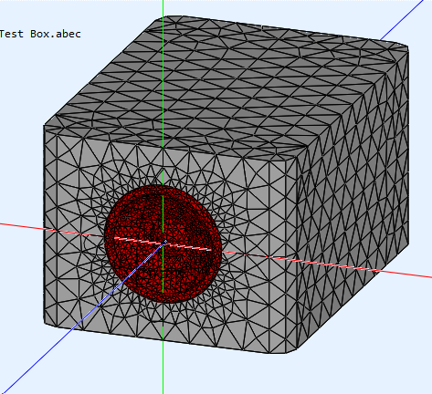
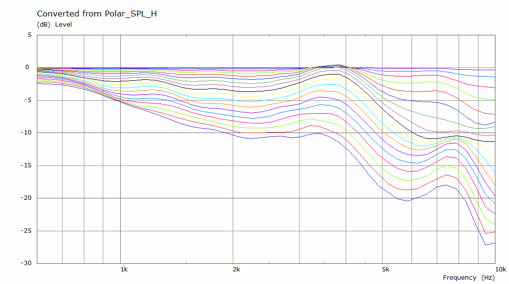
It's horizontal polars:
On to a more complex 'egg shape' box:
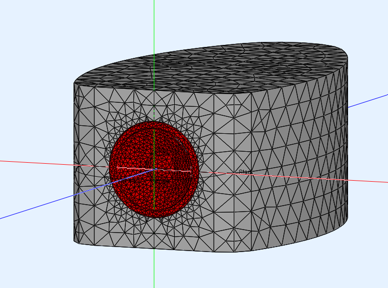
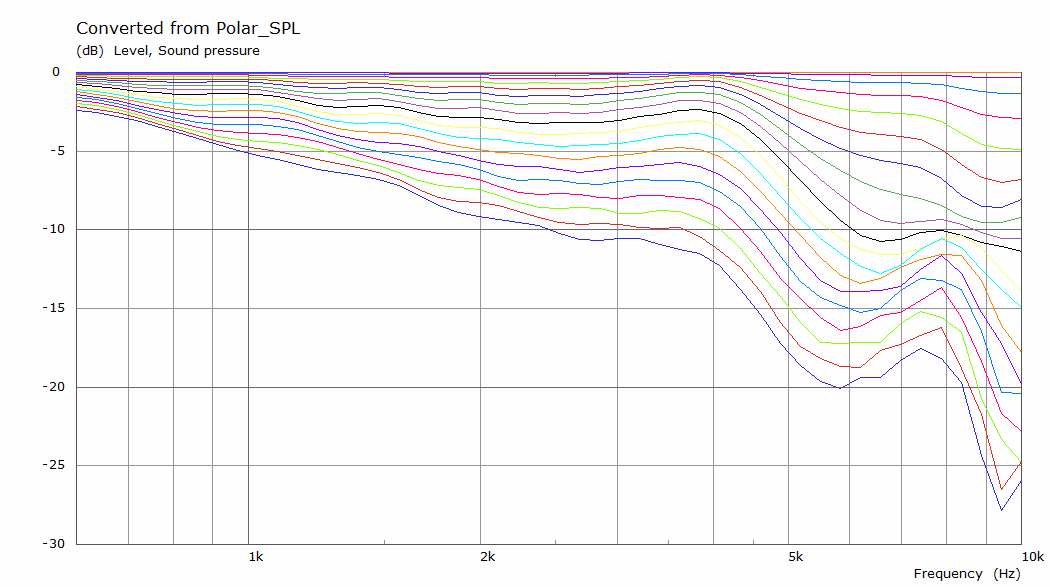
It's horizontal polars:
And finally the back-mounted driver in the 'egg shape':
It's horizontal polars:
Worth it? To me it is 😀. That last shape is what I went with, long ago, so you'll hear no complaining from me. But it might give some of you something to think about. Not aimed at anyone in particular and no pun intended.
Here's the start of the ABEC story: https://www.diyaudio.com/forums/full-range/242171-towers-25-driver-range-line-array-663.html#post6524791
(*) = sadly the pictures of that particular experiment are long gone. I found it on a German DIY forum.
More important, the outside shape does matter in my humble opinion. I envisioned a smooth egg shaped cabinet would have some advantages compared to a more regular box shaped enclosure. I wanted to avoid sharp edges and have the biggest radius I could use, flowing into the sides etc...
At a later date I stumbled upon some pictures of a back mounted driver and as it looked smooth to me I decided to hunt the internet to 'see' if it had any drawbacks. I found some evidence pointing at better behavior than flush mounted drivers(*) with a driver mounted behind a 8 mm baffle with a roundover of the edge. As I really liked the look, it is what I went with at the time.
Fast forward to some weeks ago, we were able to test the differences with ABEC. That simulation requires 3D models that are quite detailed and accurate to function well, just look at the ATH Horn thread for many samples.
In collaboration with member fluid, we decided to test the shape I have used in my arrays compared to a flush mounted driver with the same enclosure shape and a more traditional boxed shape (with roundover).
Let's see that story in pictures, starting with the simple box:
It's horizontal polars:
On to a more complex 'egg shape' box:
It's horizontal polars:
And finally the back-mounted driver in the 'egg shape':
It's horizontal polars:
Worth it? To me it is 😀. That last shape is what I went with, long ago, so you'll hear no complaining from me. But it might give some of you something to think about. Not aimed at anyone in particular and no pun intended.
Here's the start of the ABEC story: https://www.diyaudio.com/forums/full-range/242171-towers-25-driver-range-line-array-663.html#post6524791
(*) = sadly the pictures of that particular experiment are long gone. I found it on a German DIY forum.
Last edited:
Well, actually I know of a case where fibrous stuff got caught in the motor... so yes, be careful.yes, stuffing tends to "kill the sound".
Otherwise, this claim is often heard of. No one brings a holding explanation though. Or it must be that the cavity resonances added to the source signal are interpreted as beneficial.
People tend to forget a mid driver almost always operates in it's resistive frequency band only. The fundamental resonance is more a crossover challenge than an acoustic problem. The way cavity resonances are dealt with doesn't really matter, but one has to deal with them.
On the topic of internal damping, I simply watch the impedance of the 'driver in box' and compare it to the driver impedance in free air. Removing the wiggles I see in the impedance with stuffing. I do put something on the walls (wool felt worked well for me in that application) as it performed better to remove the tiny wiggles in a close up of the driver's impedance as mounted in the box. I may be one of few that runs the driver all trough it's resonance peak and wanted smooth behavior and get that peak to the lowest frequency I could. Documented in my thread, done with a test enclosure.
Hi res impedance measurement certainly reveals a lot. But I stick to the close range burst decay or CSD plot these days.
Very nice test results! This ties in nicely with some of the tweeter waveguide experiments that others on here have carried out with their 3d printed waveguides. They theorized that by horn loading the tweeter, it effectively took the enclosure out of the equation, making the cabinet boundaries more or less invisible to the driver. I wonder if you're getting the same effect by creating a "mini" waveguide for the midrange.I am one of the people that have featured a complicated internal shape for my enclosures. In all honesty, it was something I had seen once in a translam build. As I was going to do translam anyway, primarily for the outer shape flexibility, I figured it wouldn't hurt to 'play' with the inside shape as well. At the very least it gave me a varying outer wall thickness.
More important, the outside shape does matter in my humble opinion. I envisioned a smooth egg shaped cabinet would have some advantages compared to a more regular box shaped enclosure. I wanted to avoid sharp edges and have the biggest radius I could use, flowing into the sides etc...
At a later date I stumbled upon some pictures of a back mounted driver and as it looked smooth to me I decided to hunt the internet to 'see' if it had any drawbacks. I found some evidence pointing at better behavior than flush mounted drivers(*) with a driver mounted behind a 8 mm baffle with a roundover of the edge. As I really liked the look, it is what I went with at the time.
Fast forward to some weeks ago, we were able to test the differences with ABEC. That simulation requires 3D models that are quite detailed and accurate to function well, just look at the ATH Horn thread for many samples.
In collaboration with member fluid, we decided to test the shape I have used in my arrays compared to a flush mounted driver with the same enclosure shape and a more traditional boxed shape (with roundover).
Let's see that story in pictures, starting with the simple box:
It's horizontal polars:
On to a more complex 'egg shape' box:
It's horizontal polars:
And finally the back-mounted driver in the 'egg shape':
It's horizontal polars:
Worth it? To me it is 😀. That last shape is what I went with, long ago, so you'll hear no complaining from me. But it might give some of you something to think about. Not aimed at anyone in particular and no pun intended.
Here's the start of the ABEC story: https://www.diyaudio.com/forums/full-range/242171-towers-25-driver-range-line-array-663.html#post6524791
(*) = sadly the pictures of that particular experiment are long gone. I found it on a German DIY forum.
If the stuffing kills details, perhaps this is because too much stops too much the puston feedback force. I mean elastic behavior of air in a sealed volume.
As Jim, ir also like the darkforces at HTguide bar; I go for the shape I can and often it suffices. Water circuitre are also easy. Nozzle or breaked internal shapes are ideal for the theory and for the facts certainly as well. I will try in my current dev some buble plastic sheet at stuffing said to provide good result for the mids and maybe an internal two box with a variovent in the middle to henhance the virtual volume...crossing the finger it doesn't create an internal boom bass box...
If I can my cabinet will be made like the one of Wesayso...tear drop or nozzle shape are ideal..
But no data sorry.
Since it is only for mid range why not make the back breathable instead. Like using 50mm insulation slabs, can test it out using different density or thickness.
Plastic bubble pack you say Diyiggy ? There's a type that I've since which is long in shape, looks like a pillow. The flat side must be secure to the speaker box wall I presume. Sound might end up dry & bouncy. Lol
Cheers
Cheers
Cause it is changing the spl; the shape of the front curve and its low end; its group delay and phase...the patern radiation outside and so on. Me want sealed as many for mids with a Qtc between 0.5 and 0.6...preferabily.
For the wall stuffing of mid cabinet, there are testimonials of its good behavior i.e. not killing the clearness...is it ok for all the cone materials...i don't know...
Perfectly honest and perfectly legitimate to like some concept. The measurable truth (...) is quite boring. But Jim asked for measured performance. So we might try to stick to that.But no data sorry.
Plastic bubble? Hmmm...
Open cell foam is the one commonly used for absorption ( to have flow resistivity you need something 'opened' for the flow to be slowed down).
Open cell foam is the one commonly used for absorption ( to have flow resistivity you need something 'opened' for the flow to be slowed down).
I have a lot of respect for those who design successful 2-way vented box systems or FR systems. When a single driver has to manage the vented-box bass and the midrange, there is a delicate balance from the competing priorities. From my understanding, the midrange performance is enhanced by a completely filled (but not compressed) stuffing. The bass performance is enhanced by a very lightly lined enclosure. Too much stuffing, or too much in the wrong place, and we can "kill the sound". So achieving an optimal balance is not easy. It requires really good judgment and experimentation. The location of the vent internally is important relative to the location of the stuffing. The vent location is also important from the standpoint of upper frequency box and vent resonances radiating out...From the standpoint of a vented driver which must handle both bass and midrange, I can see that a multi-faceted enclosure might allow us to use less stuffing... to get a better optimization.
A midrange driver is something different... Typically high pass crossed at 200 - 600 Hz, there is no bass in the signal to the driver. There is no downside to acoustic absorption (stuffing)... yes? I am curious if anyone has subjective opinions that stuffing negatively affects the midrange... ?
GM wrote:
I have no doubt about what you say. Augerpro's research last year showed the big differences between an empty box and an intelligently stuffed one... But my take-away from that was that good stuffing did a really good job of eliminating acoustical resonances inside the box.
Thanks for the good discussion so far .............. j
A midrange driver is something different... Typically high pass crossed at 200 - 600 Hz, there is no bass in the signal to the driver. There is no downside to acoustic absorption (stuffing)... yes? I am curious if anyone has subjective opinions that stuffing negatively affects the midrange... ?
GM wrote:
They do if high enough amplitude; can stand out like 'sore thumbs' with many vintage FR drivers.
Ever measured [wide range] woofers in an empty box big enough to generate eigenmodes in the driver's usable pass band?
I have no doubt about what you say. Augerpro's research last year showed the big differences between an empty box and an intelligently stuffed one... But my take-away from that was that good stuffing did a really good job of eliminating acoustical resonances inside the box.
Thanks for the good discussion so far .............. j
Krivium;
All is about the energy, I.e. the wave length
Ifwe just needed of open foam we will not ask about the shape of the load and will talk only aboutthe stufing
And by the way the behavior is more complex as a part of a energy is absorbed whatever its open material ornot to be transformed in heat and the rest bounces in the load. You must understand the behavior is changing also with not only the WL so frequency but also with the spl; i.e. compression force behavior. So there are resonances and modes that are certainly higher as the frequencies are lowering.
Sometimes plain materialwith a mass spring mass brake is better than any foam.
But I think Jim is asking for the bigger partto break the modes...basicly where the shape plays a role.
But again as he said not easy to measure . Theory still matters...there are acoustic laws. Aperiodic is certainly easier while radiate outside but my understanding is Jim is asking for sealed mids ?
All is about the energy, I.e. the wave length
If we just needed of open foam we will not ask about the shape of the load and will talk only about the stufing
I think both ( shape and stuffing) play a role.
And by the way the behavior is more complex as a part of a energy is absorbed whatever its open material or not to be transformed in heat and the rest bounces in the load. You must understand the behavior is changing also with not only the WL so frequency but also with the spl; i.e. compression force behavior. So there are resonances and modes that are certainly higher as the frequencies are lowering.
I thought i understood the principle at works. But i'm open to be corrected in case, no issue about that from my part.
That said i have some plastic bubble sheet ( with different kind of bubble diameters and plastic (some are deeper than other)) and just made a very basic experiment: i covered my head ( ears) with it and played a slow sine sweep through my loudspeakers: the one i have are transparent ( or marginally affecting freq past 4/5khz) up to my auditory limit ( 14khz) at 90dbspl ( at listening point, i upped by 5db my usual listening level).
So except the fact i looked like someone believing ET's are coming soon ( which was fun) i think i can conclude wavelength of interest are outside the target i could see a use for them.
I agree this is not very scientifical but you could try it too it is reproducible. I won't try about spl because the condition are difficult to reproduce (spl inside a box are high) and i don't want to have tinitus tonight.
Maybe this have an effect because because of mass/sping but to me this kind of behavior are what we are looking for for soundproofing in acoustic (but the materials have more mass overall and are much more resilient(less bouncy)) and if this have an effect i would expect it to be on box resonance (structural), not really about reflections inside the box.
In other word it could have an effect on radiation of walls of the box ( kind of CLD or damping).
Same thing as eggscrate to me: there is a small effect high in freq (6k and up iirc) but does it came from the shape or the material by itself?
Anyway i don't want to stop you experimenting (and i will probably try it too!), i was just pointing a fact: for absorbtion most materials are open structure.
Sometimes plain material with a mass spring mass brake is better than any foam.
But I think Jim is asking for the bigger part to break the modes...basicly where the shape plays a role.
I agree but as i said this is valid in certain circumstances in acoustic but i dont see this case to be one of them ( do we need decoupling which is where neoprene closed cell foam are regularly used?).
You seems to focus on foam but most ( if not all materials) used for stuffing are 'open' structure, flow resistivity and all...
To have non parallel wall doesn't break modes, it just change the way they are positioned within a box ( or a room). Where it could help with mid and high is to make reflections less specular.
Moderator Tinitus (RIP) posted some pictures of a classical three way monitor he built where he used cardboard matrix on opposed wall to driver to help scattering. Same goal, different approach.
Last edited:
- Home
- Loudspeakers
- Multi-Way
- Midrange Enclosure Internal Shape