Just had to bump this one for new readers 🙂
I've spent countless hours optimizing ground planes, regulators and the whole schabang, and this guy goes ahead and makes something so good, yet so simple. Kudos!
Thanks; I call it the "!#*% it" design approach. That means if a project doesn't turn out as planned, I just say "!#*% it". 😀
Seriously though, I think I just get lucky a lot. I wish I knew enough to be able to "optimize ground planes" and such. 😱
Anyone did compared this dac to a TDA1541 dac ?
Sorry, never heard one.
Just had to bump this one for new readers 🙂
Ok, so I didn't bump it, I just forgot to look for page 2... Still worth it 😉
Thanks; I call it the "!#*% it" design approach. That means if a project doesn't turn out as planned, I just say "!#*% it". 😀
Seriously though, I think I just get lucky a lot. I wish I knew enough to be able to "optimize ground planes" and such. 😱
Wish I knew that, too... I'm just trying to remember some old tips from pwatts, and winging it from there. With any luck, it'll sound OK. And a Zapfilter from L C Audio takes care of the I/V for me, so I don't have to muck about with that. As long as it sounds better than my old Pioneer CDP with a hopeless powersupply feeding PSU sensitive PCM1702, I'll be almost happy. The "!#*% it" approach doesn't work too well when it takes about a month to have the boards made...
Ok, so I didn't bump it, I just forgot to look for page 2... Still worth it 😉
Does that mean you missed page 4?
The "!#*% it" approach doesn't work too well when it takes about a month to have the boards made...
Yeah, that's why I try to keep my projects simple enough to DIY.
I can't even make acceptable files for a board house to use anyway. 😱
Does that mean you missed page 4?
Nope, I've just set it up to view 50 posts per page. Less clicking that way.
Yeah, that's why I try to keep my projects simple enough to DIY.
Yeah, I did that for a while, but I could never get my PCBs to look good. And I have no idea how to make through-plated holes like vias. How did you do it?
I can't even make acceptable files for a board house to use anyway. 😱
Well, you sure have the skills! Many board houses, like Olimex that I use, accept .brd files straight from Eagle. Just configure a design rule file to fit their standards (10mil minimum tracks etc.) and you're good to go. I dare say it's better for the final design, although it makes it difficult and slow to experiment.
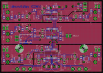
I'm attaching a semi-finished screenshot of my DAC board with SRC. I'll make one without SRC, too, I have a feeling it won't make much difference with a good source like the Lynx AES16. The relay by the left screw switches between 96 and 192 kHz, so I can hook them all up to a simple IR board.
Attachments
Last edited:
And I have no idea how to make through-plated holes like vias. How did you do it?
Real DIY vias require special tools and expensive supplies, and even then you can only make them so small; not worth it IMO.
I just use a small pad with a hole in it and the use a very thin copper wire going through the board. I solder in a length easy enough to work with and then cut off the extra.
Many board houses, like Olimex that I use, accept .brd files straight from Eagle.
Eagle and I agree to disagree with each other. It promised not to cause me any more headaches as long as I promised not to use it. Maybe some day we will learn to get along. 😛
Nice layout by the way!
Yeah, Eagle has a steep learning curve. A whole lot of seemingly illogical and unfamiliar ways of doing things, but if you accept a little headache it might be worth it. I'll see if I can find a tutorial that actually works if you want.
What do you use now?
What do you use now?
Yeah, Eagle has a steep learning curve. A whole lot of seemingly illogical and unfamiliar ways of doing things, but if you accept a little headache it might be worth it. I'll see if I can find a tutorial that actually works if you want.
What do you use now?
The problem I was having with eagle is that it's not really designed to make layouts for boards that will be hand made (or maybe I just don't know enough about the program to do so effectively).
I use (abuse) a program called Pad2Pad. It's made by a company that really expects you to have the boards made through them. I use it as a glorified "paint" program though. I don't bother with nets or autorouting; I lay every component, trace, pad, etc. manually. It's really nothing more than a graphic when it's done. 😱
I still use an old student version of AutoCad in the same way. I like it because 1) I (kind-of) know how to use it and 2) it does give you good control over line widths and pad placement. Someday I hope to convert to a PCB program, but previously, I tried a couple of freeware programs and found them more difficult or limited. Next time, I'll give Pad2Pad a try. I have also heard good things about ExpressPCB (same deal - free software intended for ordering boards, but I believe you can also print your own toner etching masks with it)
Last edited:
Hi,
nice little project indeed ;-) Just two little remarks. First the PCM puts out a center current plus minus a signal current. This leads to an voltage offset over the I/V-resistors, which depends on the resistor values. Second, I also prefer the passive I/V conversion via firstclass resistors, but You might think of much smaller values than the 420Ohms in Your schematic. The DAC-outputs of the PCM1794A feature protection diodes which start conducting already slightly above 100mV. The results are quickly increasing distortion values. As long as You stay below 30Ohms the THD-values can be even slightly better than those that BB/TI claim in their Datasheet!
jauu
Calvin
- Status
- Not open for further replies.
- Home
- Source & Line
- Digital Source
- Micro DIR9001 + PCM1794A DAC