For those interested; there is an article on MFB in the September and October issue of electronics world.
The sepetember issue is more theoretical and the October issue has a more DIY character (boxe design ,MTM, and practical schematic).
grtz
Simon
The sepetember issue is more theoretical and the October issue has a more DIY character (boxe design ,MTM, and practical schematic).
grtz
Simon
Yes.
This designs uses the EM returned from the speaker, and feeding it "postively" back to the Amp.
grtz
Simon
This designs uses the EM returned from the speaker, and feeding it "postively" back to the Amp.
grtz
Simon
Hi Simon
What is described there is the increase of damping of the driver's fundamental resonance by generating a negative output resistance (has also been discussed here in the damping factor thread).
Though the idea isn't bad at all I wouldn't call it MFB since the cone-motion is nowhere measured directly.
While the article isn't bad at all, I wonder why it is publiushed anyway, since another, quite similar article was already published not too long ago in the same magazine.
Regards
Charles
While the article isn't bad at all, I wonder why it is publiushed anyway, since another, quite similar article was already published not too long ago in the same magazine.
What year and number ??
Missed that one !
grtz
Simon
Hi Simon
I just found it:
Year: 1998
Month: November
page: 955
title: "Going lower"
Author: Russel Breeden
Although it isn't as detailed as the new article there is enough info for anyone "known in the art" to build such a thingie.
The principle by itself is quite old already, the oldest article mentioned I could find is the one by K.E. Stahl describing the ACE bass method.
Regards
Charles
MFB - Part 1/2
Hello Folks!
I think it's time for me to give a contribution of one more schematic for this forum.
I had one of these MFB speakers 25 years ago...Has I remember they have amazing bass.
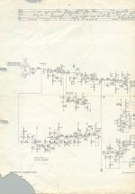
Here is the schematic of this active speakers from Philips.
Regards,
Jorge Santos
Hello Folks!
I think it's time for me to give a contribution of one more schematic for this forum.
I had one of these MFB speakers 25 years ago...Has I remember they have amazing bass.
Here is the schematic of this active speakers from Philips.
Regards,
Jorge Santos
Attachments


Re: MFB - Part 2/2
Could you send me a better-quality copy of this schematic? It is very difficult to recognize parts in this copy and I am very interested to see some of the circuits.
Thank you very much!
moamps@yahoo.com
Tube_Dude said:
Could you send me a better-quality copy of this schematic? It is very difficult to recognize parts in this copy and I am very interested to see some of the circuits.
Thank you very much!
moamps@yahoo.com
<a href="http://www.euronet.nl/users/temagm/audio/">Geert Meddens</a> home page has the full service manual for the MFB544 availble for download, its 3.87 Megs.
Regards
James
Regards
James
Re: Re: Mfb
Elektor had a project long time ago. They attached a piezo element at the dust cover of the speaker. This sensor reacts on force (pressure). If it's attached at the speaker you will get acceleration as output signal.
Constant acceleration = constant sound pressure level.
The acceleration signal is feed back to a normal regulator (opamp + power amp).
I have tested this myself with a 5" wideband speaker, worked nicely. The sensor was a piezo element from a greeting card.
If you press your thumb on the element you will 50-100 V!
I started also a 12" project but didn't come so far....nothing has happened since 1987...
planet10 said:MFB?
can you expand this TLA for us
Elektor had a project long time ago. They attached a piezo element at the dust cover of the speaker. This sensor reacts on force (pressure). If it's attached at the speaker you will get acceleration as output signal.
Constant acceleration = constant sound pressure level.
The acceleration signal is feed back to a normal regulator (opamp + power amp).
I have tested this myself with a 5" wideband speaker, worked nicely. The sensor was a piezo element from a greeting card.
If you press your thumb on the element you will 50-100 V!
I started also a 12" project but didn't come so far....nothing has happened since 1987...
All these techniques have been around a long long time:
Microphone feedback
Accelerometer feedback
Dual voice coil feedback
Current sensing feedback
(Have I missed any?)
They all work, and they all have their limitations: specifically,
instability when applied for more than a few dB.
Microphone and current sensing are my favorites, but I
have to admit that I've enjoyed all of them at one time or
another. Of the bunch, the accelerometer technique is
the biggest pain in the butt.
I've got at least two or three of those old Philips speaker service manuals somewhere around the house. As I recall, they required specially made woofers. How applicable their circuits would be to DIY efforts is questionable. Again, from memory, they seemed more complicated than necessary.
You can also do a direct read from the cone with a tiny coil and magnet rig glued directly to the cone itself. Essentially, you're making a dual voice coil woofer where there was only one before. No huhu, Lulu. The nice thing is that since you don't need lotsa current, the coil or magnet can be quite small, hence low mass. Also, you're away from the driving coil, with its attendant EMF fields. Don't assume that what the voice coil is doing is an accurate reflection of what the cone is doing (although it's a whole lot better than no read at all).
I've still got it in mind to use the guts out of an old Grado cartridge attached to the back of the cone, but never seem to find the time.
The dedicated accelerometer chips are--or at least were a couple of years ago--frighteningly expensive. Maybe you guys have more money than I do, but when a chip costs more than $20, I start scratching my head and trying to figure out cheaper ways to do things, particularly when I'll be running twelve independent feedback loops. Ugh. I'd rather spend that money elsewhere.
Maybe the chip prices have come down. I haven't checked recently.
The piezos have a bit of a phase shift problem that you have to work around. The last design I saw used all pass filters to do the trick, but I've got a different strategy in mind. I promise to get to it right after I finish building the speakers I'm working on, a pair of Aleph-Xs, the line stage I've promised to drive the Aleph-Xs, the phono stage...
Grey
GIF, not JPEG.
If you scan a schematic for posting, increase the contrast so it only has 2 colours, not many shades like a picture, and then save and post it as a GIF file. It will be way smaller, or conversely you can make a much more detailed pic for the same 100K file size limit.
If we could only post Group 3 TIFF files... for line drawings they are *really* compact.
GP.
Reflected laser light
I wonder if you could make a setup that aims a small beam from one of those hand-held laser pointers onto part of the cone, presumably near the centre, and it reflects back off a white or shiny section to some kind of optical sensor. Maybe the further away the sensor is, the greater the beam deflection and so the greater the sensitivity. Just an idea...
GP.
Re: GIF, not JPEG.
gifs also do not suffer from lossy compression and jpeg artifacts -- the "fuzz" you see around letters and lines in a B&W image.
Sometimes 4 shades of grey work better than just 2 -- the extra 2 greys antialias the abrupt tranistion from black to white.
dave
gifs also do not suffer from lossy compression and jpeg artifacts -- the "fuzz" you see around letters and lines in a B&W image.
Sometimes 4 shades of grey work better than just 2 -- the extra 2 greys antialias the abrupt tranistion from black to white.
dave
- Status
- Not open for further replies.