They will vary with the main volume control. Fixed in relation to the primary outputs.
Got it! Thank you!
Hey all, I'm embarking on my DCB1 build with Muses volume and I have a draft BOM, I'd appreciate any advice before I order.
My two main issues are:
- unmatched JFETs, i wasn't able to find these so I have a matched octet on there but they are pretty pricey
- Muses chip is backordered until late December, if anyone knows where else I can get one please let me know
My two main issues are:
- unmatched JFETs, i wasn't able to find these so I have a matched octet on there but they are pretty pricey
- Muses chip is backordered until late December, if anyone knows where else I can get one please let me know
Attachments
About Muses volume if wait is long for the the chip to be restocked, Hi-End Audio Modules | United States | Academy Audio Inc has some assembled pcb solutions, even with controller and remote. From a quick look some may work with +/-10V already provided from the Mezmerize on its rails test pads. The few mA consumed by the vol system should be no burden to the powerfully biased shunt regs. An extra 5V line for the controller will be needed though. Can be brought down from a higher rail with an LM7805.
NAC Semi in Florida has unmatched LSK170s Link
Why listing IRFP250? It has high parasitic capacitance. Mouser has the original in stock (844-IRFP240PBF).
Thank you, good catch on the IRFP, I have no idea how the 240 got changed to 250, I have replaced with the correct part
And thanks for the lead on umatched JFETs, I appreciate it
About Muses volume if wait is long for the the chip to be restocked, Hi-End Audio Modules | United States | Academy Audio Inc has some assembled pcb solutions, even with controller and remote. From a quick look some may work with +/-10V already provided from the Mezmerize on its rails test pads. The few mA consumed by the vol system should be no burden to the powerfully biased shunt regs. An extra 5V line for the controller will be needed though. Can be brought down from a higher rail with an LM7805.
Thanks for this, I looked into it and this vendor is local to me, so I reached out to them. They have a standalone VCU that they say will work well:
VCU, Hi-End MUSES(R) Micro Volume Control Board (No controller needed) | academyaudio
I'm planning to add one to my SSE as well, just working out the details on how to power it correctly in both applications.
Looks like these are on backorder as well, no estimated date on Mouser but I saw 12/1 on Newark, is there a substitution?
1N4007-E3/54
1N4007-E3/54
Its a very common diode type used here as fly-back absorber for the coils in the relays. You can use 1N4006 instead: 625-1N4006-E3/54 Mouser number in stock.
Its a very common diode type used here as fly-back absorber for the coils in the relays. You can use 1N4006 instead: 625-1N4006-E3/54 Mouser number in stock.
Thanks I figured it was common but wanted to confirm
Thanks I figured it was common but wanted to confirm
To can pass the relay's coil current is basically enough spec for picking a diode type. Although the original 1N4001 was doing the job I recommended 1N4007 over it in the 2018 BOM because its ubiquitous and more likely to already be in one's spares stash. It also has almost half the junction capacitance (1N4005-07 8pF vs 1N4001-04 15pF).
Why diodes are used around relay coils: Back to Basics on flyback or snubber diodes
This was very informative, thank you. If there are any other resources like this that you have I’d be interested.
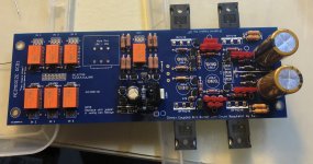
Made some good progress today. Waiting on the 4 remaining caps and the AC connector. Also I forgot to order the 270 ohm resistor next to the jumper.
The long jumper in the PSU area I used a resistor lead is that ok?
Also wondering where on the board I would tap from for the 2nd output, I know it’s the input side of the 220 ohm resistors but I can’t figure out which end that is.
The long jumper in the PSU area I used a resistor lead is that ok?
Also wondering where on the board I would tap from for the 2nd output, I know it’s the input side of the 220 ohm resistors but I can’t figure out which end that is.
Attachments
You don't need 270 Ohm resistors. Those are instead of jumper to can use 5V relays. But you use 12V relays.
Your other jumper wires are also alright. They are used as a reinforcement.
Don't tap from the route of the 220 Ohm output resistors for the secondary outputs if you need the output relay's action on those outputs too. Tap from the main outputs instead. Otherwise for AC input coupled second amp, the points are between drain and source in each signal pair of JFETs where meeting those inside pair 220 Ohm resistors input pins.
You don't need 270 Ohm resistors. Those are instead of jumper to can use 5V relays. But you use 12V relays.
Your other jumper wires are also alright. They are used as a reinforcement.
Don't tap from the route of the 220 Ohm output resistors for the secondary outputs if you need the output relay's action on those outputs too. Tap from the main outputs instead. Otherwise for AC input coupled second amp, the points are between drain and source in each signal pair of JFETs where meeting those inside pair 220 Ohm resistors input pins.
To be honest I don’t know enough to know if I need the relay action or not, I’m assuming I do. Earlier I had mentioned that I’ve seen people branch the 2nd set off of the first set with a 220 ohm resistor in between and you said:
its better to feed signal for the second set of output resistors from the input side of the first set, not making them additive to those
So I’m trying to figure out where that would be on the board.
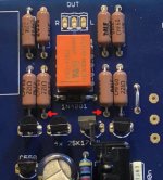
Output impedance wise its better. But that also skips the output relay and I must let you know about it too. If you are not sure what you will connect on the secondary output is DC safe indeed (capacitor input coupled and/or with DC sensor protection for speaker) don't do it. Do like the others do. Anyway, the raw output points on the board are those two nodes pointed with the red arrows.
Attachments
Output impedance wise its better. But that skips the output relay and I must also let you know about it too. If you are not sure what you will connect on the secondary output is DC safe indeed (capacitor input coupled and/or with DC sensor protection for speaker) don't do it. Do like the others do.
Ok got it, most likely would be a powered subwoofer so probably not DC safe, right?
Can I ask one other possibility dumb question? Why the resistor between the outputs? What happens if I just use regular wire? Or run a 2nd set of wires off the output?
Depends on how each subwoofer is designed. If protection systems are not listed in its futures set they probably don't exist. When in doubt someone needs to disassemble and look or having its service manual schematic to surely tell.
The resistor between outputs coming from same signal source offers buffering impedance to the routes of different gear for interacting less. Else there might be some THD created.
The resistor between outputs coming from same signal source offers buffering impedance to the routes of different gear for interacting less. Else there might be some THD created.
Is the sight down after the modification. I’m trying to open up the bill of materials for a build and I keep getting a page error?
- Home
- Amplifiers
- Pass Labs
- Mezmerize DCB1 Building Thread