When soldering I try to get heat into the pad and then the component, my hands aren't as good as they were a few years ago, maybe I should leave diy alone....
Goals are:
1. About 1.75V voltage drop across Rset resistors pins. Even 1.65V is normal
2. About +/-10V output voltage at the end of the regulators (three test pads)
3. Less than 5mV DC offset on each signal output after the regs are restored
Suspicious points:
1. BC560 in the negative reg that was giving high output voltage (replace it)
2. IRFP9240 Mosfet near Rset in the positive regulator of burned Rset (replace it)
3. Any discontinuity between components due to rework. Turn around the PCB and verify the lanes with the DMM's continuity buzzer.
When testing:
Quickly check voltages and temperatures. Voltage drops on Rset resistors first. If too high, there is over-current. Rset and Mosfet(s) should become very hot fast in this case. Shut down soon. Use a dim bulb tester for general safe power up practice if you got one.
That 1.75V on Rsets is created from the three Leds combined forward drop minus Mosfet Vgs voltage. Vgs happens between Mosfet pins 1&3. If a near Rset located Mosfet has far lower or far higher Vgs than its opposite in the non components burning reg, its probably broken. Or a pcb point is broken. Normal Vgs in this circuit's ~200mA constant current for our Mosfet types is about 4V DC.
I don't think so but just removing the Rset resistors looked like it pulled something up with it.
Should there be a contact between Rset pads and ground? Do I need to run a wire from Rset to ground?
Normally no, that would be a short. Is it zero Ohm measurement or just beeps for low? Because there are components installed the DMM maybe finds a low impedance path. DMMs beep below 50 Ohm or about, not at strictly zero.
Difficult not to be fixable with little wires reestablishing paths. It does not have inside copper layers or close pitch high pin count ICs and the like.
Also check visually for solder bridges in unlikely places. Even in the audio section of the board. Use magnifier and torch. Maybe the DMM buzzes for a true short reason.
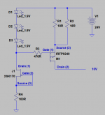
Here's the positive polarity constant current creating subsystem. Where your combined Rset 18R//18R has burned. You can verify its not broken somewhere for interconnections as a circuit, with the DMM's continuity buzzer tracing on pins and resistor measurements.
Attachments
I have an amp that has a fairly low input impedance. Can't tell exactly what it is but it is pretty low as on the input there is a coupling transformer with 600 ohm on both windings. Center tap wired to ground and each secondary outs connected to the grids with no grid leak resistors.
Is it feasible to swap the 220R out resistor (R2/R8) to achieve a lower output impedance? Let's say I would use 50R
Another thing I'd like to know if I can change R4/R3 to let's say 1M so I could use a pot that I already own a 100K TKD rather than the 20k Alps
Is it feasible to swap the 220R out resistor (R2/R8) to achieve a lower output impedance? Let's say I would use 50R
Another thing I'd like to know if I can change R4/R3 to let's say 1M so I could use a pot that I already own a 100K TKD rather than the 20k Alps
Last edited:
I have an amp that has a fairly low input impedance. Can't tell exactly what it is but it is pretty low as on the input there is a coupling transformer with 600 ohm on both windings. Center tap wired to ground and each secondary outs connected to the grids with no grid leak resistors.
Is it feasible to swap the 220R out resistor (R2/R8) to achieve a lower output impedance? Let's say I would use 50R
Another thing I'd like to know if I can change R4/R3 to let's say 1M so I could use a pot that I already own a 100K TKD rather than the 20k Alps
Both your experiments to perform are feasible. Only use no longer than necessary output interconnects and confirm there is no line out signal instability when connected to the power amp by using a scope if you got one.
*The audio input transformer just reflects the impedance seen on its secondary when 1:1 or dividing it by the turns ratio squared if >1:1.
As to how much input impedance there actually is you can characterize by driving the amp with a known Zout sinewave gen adding series resistance until its output level halves. ZoutTotal then equals the input impedance it sees.
Goals are:
1. About 1.75V voltage drop across Rset resistors pins. Even 1.65V is normal
2. About +/-10V output voltage at the end of the regulators (three test pads)
3. Less than 5mV DC offset on each signal output after the regs are restored
Suspicious points:
1. BC560 in the negative reg that was giving high output voltage (replace it)
2. IRFP9240 Mosfet near Rset in the positive regulator of burned Rset (replace it)
3. Any discontinuity between components due to rework. Turn around the PCB and verify the lanes with the DMM's continuity buzzer.
When testing:
Quickly check voltages and temperatures. Voltage drops on Rset resistors first. If too high, there is over-current. Rset and Mosfet(s) should become very hot fast in this case. Shut down soon. Use a dim bulb tester for general safe power up practice if you got one.
That 1.75V on Rsets is created from the three Leds combined forward drop minus Mosfet Vgs voltage. Vgs happens between Mosfet pins 1&3. If a near Rset located Mosfet has far lower or far higher Vgs than its opposite in the non components burning reg, its probably broken. Or a pcb point is broken. Normal Vgs in this circuit's ~200mA constant current for our Mosfet types is about 4V DC.
Good morning, resistors arrived yesterday and today I have some spare time.
Ive checked for discontinuity and can't find any.
No solder bridges.
I've replaced the BC560.
Fitted a 2W 10 Ohm at Rset.
Upon startup all that didn't light up were the 3 LEDS near the Rset that burnt out (irfp9420 side of the board). Before I could measure the voltage across the Rset resistor it started to burn out so I switched off.
I've replaced the leds (two weren't working) and tried again, same result although i briefly got a reading of -10.6v across Rset.
What will be the next item to check?
Check if the Leds are still working. Check if the K170 Leds driver still shows normal RDS. Replace that K170 and IRFP9240 if in doubt. Rset burns because a large voltage appears across it. Normal voltage will be about 1.7V DC if both the three Leds are lit and the Mosfet has normal Vgs.
All continuity is true to circuit in post #2489?
It is.
Check if the K170 Leds driver still shows normal RDS.
How do I do this?
Replace that K170 and IRFP9240.
Done the IRFP9420 (second time), which k170?
It is.
Check if the K170 Leds driver still shows normal RDS.
How do I do this?
Replace that K170 and IRFP9240.
Done the IRFP9420 (second time), which k170?
RDS is how many Ohms between drain and source (pins 1&3) when no power is applied. Shows if open or shorted, but it wouldn't guarantee that the gate is intact as well. An average BL will show about 35 Ω.


- Home
- Amplifiers
- Pass Labs
- Mezmerize DCB1 Building Thread