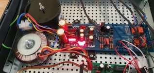
I've changed position of Jfets in one chanel and now with -10/+10V supply I've got -3.4mV left chanel and -4.6mV right chanel. By either lowering negative rail to 8V, or increasing positive rail to 13.5V, I can trim offset down to around 0.6mV/-0.6mV in both chanels. Is such asymetry of voltage correct?
Only problem is that if you will push the output beyond 8V, one peak it will clip asymmetrically.
Is it possible to configure this preamp with multiple outputs? I need either two fixed volume outputs, or one fixed and one variable.
You can install a second pair of output RCA via 220 Ohm in line resistors. Tapping signal from the input pins of the main output 220 Ohm resistors.
OK, here's another crazy question. What if I wanted one input to always be at a fixed output. All the other inputs would be variable, but one of the inputs would always output as fixed. Is that feasible?
That's about signal routing configuration. Not particular to a core circuit. You may look in service manuals of classic integrated amps as examples of routing for tape monitor loops, REC outputs, etc. You may choose passive extra routing or buffered. It would take four DCB1 channels for establishing always differently handled stereo routes, attenuated and non attenuated, but still buffered to their outputs.
Yes, pots are audible. In DCB1 because of no gain and pot buffering they are just not as obvious as in other preamps. In DCG3 they are more critical for instance.
Any alternatives to Vishay 47 ohm and 100 ohm resistors in the psu section (ccf07 series 0.5w) as I can't currently get them
Everything built and connected but only one channel works. What steps do I need to follow to diagnose it?
Putting the multimeter on the 3 pads gives 23.65v on one channel and 1.05 on the other.
If I put probes on two of the pads for one of the IRFP9240PBF then 5 more leds light up.
Putting the multimeter on the 3 pads gives 23.65v on one channel and 1.05 on the other.
If I put probes on two of the pads for one of the IRFP9240PBF then 5 more leds light up.
It's the top left IRFP9240PBF that will light the 5 leds to the right of it if I put probes from the multimeter on the two left hand pads.
First check with the DMM in AC mode if the transformer secondaries are correctly wired to the AC input connector giving ACV-Zero-ACV (zero in the center screw).
It's the top left IRFP9240PBF that will light the 5 leds to the right of it if I put probes from the multimeter on the two left hand pads.
But the associated LEDs triplet remains dark?
But the associated LEDs triplet remains dark?
It does, I'll check the AC input later. I assume you mean probes on two outer AC screws should give 20v plus and one on an outer and the other on the centre screw gives 0v?
Probes on the outer screws should give 30-34VAC for a nominal 15+15VAC Tx. Between center screw and each outer should give half those ACV.
Also see if your DMM in diode check mode can light up an LED. If it can you may try probing each LED in the triplet to see if its working or not. Red on anode. Else use a 9V battery and crock leads to briefly touch their pins. No need to remove them from the board but access to the soldered side is needed. Leave that for after checking the transformer connections if no resolve.
Probes on the outer screws should give 30-34VAC for a nominal 15+15VAC Tx. Between center screw and each outer should give half those ACV.
Got 36v across the outers and 18v between either outer and centre screw. I wired it as a centre tap on the transformer, 2 outer leads to outer screws and 2 centre leads joined into centre screw.
I'll try the leds tomorrow. Thanks for your help
- Home
- Amplifiers
- Pass Labs
- Mezmerize DCB1 Building Thread
