This'll be interesting as there's sometimes a need for a 'buffer bracket' around some of the less conventional volume controls similar to the 'Truth' preamp for example, etc.
On another query, would there be any benefit in adding Elvee's "De-Noizator" filter to your 'L-Adapter' regulator?
On another query, would there be any benefit in adding Elvee's "De-Noizator" filter to your 'L-Adapter' regulator?
You will lose the shunt character and you will be listening with LM317 sans that chip's original noise in that case.
Ah, I was thinking more about adding it to the output of the L-adapter regular to see if it would improve the performance/noise after the Siklai filter, not adding it to the DCB1, sorry for the miscommunication.
My misreading. I don't know, try it. Remember to set L-A Vout as much higher as needed to keep De-No in regulation. But L-Adapter is mainly for high current consumption applications, if those will be called can the addition pass as much current?
Will do - it'll be interesting if it works okay and actually makes a difference - the L-Adapter is for the First Watt F6 amp running at 2 channels at 1.7A, 24v, using 2 of the standard circuits.
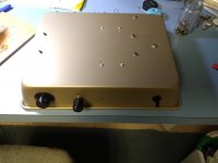
$7 piece of cake
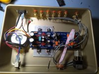
I couldn't wait for a proper enclosure and I thought a cardboard box was probably a bad idea on this one, too many connectors/knobs/heatsinks. I got a cake pan and went at it with a step-bit for all the holes.


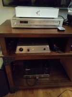
I listened to some vinyl last night (w/UFSP as the source) and it seems like a definite improvement over my old Hafler pre.
I couldn't wait for a proper enclosure and I thought a cardboard box was probably a bad idea on this one, too many connectors/knobs/heatsinks. I got a cake pan and went at it with a step-bit for all the holes.


I listened to some vinyl last night (w/UFSP as the source) and it seems like a definite improvement over my old Hafler pre.
So when the LEDs fire up its literally a flash in the pan. 🙂
Traditional makeshift diy is cool.
That Hafler jfet preamp is no slouch so finding a definite improvement over it is double nice. 🙂 🙂
Traditional makeshift diy is cool.
That Hafler jfet preamp is no slouch so finding a definite improvement over it is double nice. 🙂 🙂
That is wonderful!
I remember reading in one of Papa's articles of someone building an A40 on a cake pan.

I remember reading in one of Papa's articles of someone building an A40 on a cake pan.

I appreciate the encouragement - My wife said "is that what you've been working on... is that a cake pan?" good thing is she is use to crazy creations showing up in the livingroom.

I used the matched quad from punkydawg that was ~9ma idss in the audio section and ended up with -1.1mV and -1.0mV DC offset on the output. Overall seems like a great upgrade in my system. Now I just need to get the 6-24 crossover and a pair of F6 built.

I used the matched quad from punkydawg that was ~9ma idss in the audio section and ended up with -1.1mV and -1.0mV DC offset on the output. Overall seems like a great upgrade in my system. Now I just need to get the 6-24 crossover and a pair of F6 built.
Last edited:
YES! here is the thread:The Cast Iron Griddle Amp - a Budget Conscious Heatsink SolutionOff-topic:
Didn‘t XKR made a power-amp on a frying-pan?
Dropbox - Finmez1.JPG - Simplify your life
I built this in 2018 and it was the best thing ever.
But I tried it again recently and found the volume control unreliable, switching from low to maximum just by touching the control. The effect could be reproduced by touching the input wires too. Testing seemed to show the volume pot was intermittently switching from 20kR to 0R.
A bit depressed and not knowing where to start, I browsed around, somwhere someone said "the pcb pins can be tight and forcing them in can break the continuity between top and bottom".
This might be my problem? I can probably reflow the solder for the pins top and bottom without dismantling the whole thing using a flux pen.
What do you think?
Its not a systematic fault in DCB1 builds I could give info about, at least I don't remember a PCB eyelets related problem reported in the threads. I might be wrong, someone else may have specific info. In any case its a practical fault and it takes inspection with the meter while pulling and pushing related cables with medium force until finding the weak spot.
Can be the pot's rotation contacts alone. Or a tiny fracture on the main PCB or on the pot's wafers. Or a cold joint wire connection to them. Then to reflow it, jumper it, change something. If all joints continuity seems good, substitute with a pot you might have in a spares box to compare if the now one developed a mechanical fault. Any quality or kΩ value will do for such a basic test.
Can be the pot's rotation contacts alone. Or a tiny fracture on the main PCB or on the pot's wafers. Or a cold joint wire connection to them. Then to reflow it, jumper it, change something. If all joints continuity seems good, substitute with a pot you might have in a spares box to compare if the now one developed a mechanical fault. Any quality or kΩ value will do for such a basic test.
Thanks Salas,
I remember now the eyelet issue was on some ALWSR boards. I think my black Mez is single sided anyway. The fault seems to have corrected itself now. Maybe exercising the volume pot?
Chris
I remember now the eyelet issue was on some ALWSR boards. I think my black Mez is single sided anyway. The fault seems to have corrected itself now. Maybe exercising the volume pot?
Chris
Most likely a contacts issue that self cleaned. If there is access to its innards spray some Deoxit in it as well.
What is allowed voltage offset at the output in the Mezmerize follower buffer ?
I've got 5.6mV in one chanel and -8.9mV in the other.
I've got 5.6mV in one chanel and -8.9mV in the other.
- Home
- Amplifiers
- Pass Labs
- Mezmerize DCB1 Building Thread