- Would it be okay if I use the Antek AS-4434 where the 2x34V supplies a classdaudio Heavy Duty DC power supply and the 2x15V supplies the Mezmerize board?
Thanks Salas. Will the AS-4434 work in the above configuration?
Why not? It has 15+15V taps I see. Tie the inner brown & orange to the middle point of DCB1's Tx connector and the remaining brown & orange ones to its side inputs each.
Mosfet substitution
Salas,
I hate to ask this if it has been answered some where else, but here goes.
I bought several parts kits from Teabag for the Salas SSLV1.1 BIB and I have some kits left over that I thought at the time I could use in the Mezmerize DCB1 and Hypnotize boards.
Of course the Mosfets are different and was wondering if I could plug in the IRF9610 / IRF610 and IRF9530 / IRF530 Mosfets in place of the IRFP9240 and IRFP240 Mosfets? If so, what other resistor values need to be changed?
Thanks as always for your help.
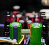
By the way, I am building your: Salas Simplistic NJFET RIAA using the Salas SSLV1.1 BIB regulators boards and the Mezmerize DCB1 for the preamp/selector and finally an electronic crossover using the B1 type buffers in a 24 db per octave 2 way crossover. I will use a pair of the Hypnotize boards (one per channel) to power all the B1s in the crossover (8 per channel), see attached, all in one case,
I will build an out-board case for the transformer with bridges, rectifiers and caps.
Your thoughts are alway appreciated.
Rush
Salas,
I hate to ask this if it has been answered some where else, but here goes.
I bought several parts kits from Teabag for the Salas SSLV1.1 BIB and I have some kits left over that I thought at the time I could use in the Mezmerize DCB1 and Hypnotize boards.
Of course the Mosfets are different and was wondering if I could plug in the IRF9610 / IRF610 and IRF9530 / IRF530 Mosfets in place of the IRFP9240 and IRFP240 Mosfets? If so, what other resistor values need to be changed?
Thanks as always for your help.
By the way, I am building your: Salas Simplistic NJFET RIAA using the Salas SSLV1.1 BIB regulators boards and the Mezmerize DCB1 for the preamp/selector and finally an electronic crossover using the B1 type buffers in a 24 db per octave 2 way crossover. I will use a pair of the Hypnotize boards (one per channel) to power all the B1s in the crossover (8 per channel), see attached, all in one case,
I will build an out-board case for the transformer with bridges, rectifiers and caps.
Your thoughts are alway appreciated.
Rush
Attachments
It does not seem like it will be oscillating if you keep everything the same but the Mosfet types, its compatible theoretically. Take care to insulate the TO-220s well, they aren't as easy for that as the TO-247s. It will be a bit higher impedance, certainly not put together and critically judged for a DCB1 as a whole in the development stage, can be good enough I guess, don't know more. Certainly cheaper and a tad uglier.😀
Good luck with the assortment as a total, and keep us posted.
Good luck with the assortment as a total, and keep us posted.
It does not seem like it will be oscillating if you keep everything the same but the Mosfet types, its compatible theoretically. Take care to insulate the TO-220s well, they aren't as easy for that as the TO-247s. It will be a bit higher impedance, certainly not put together and critically judged for a DCB1 as a whole in the development stage, can be good enough I guess, don't know more. Certainly cheaper and a tad uglier.😀
Good luck with the assortment as a total, and keep us posted.
Thank you Salas,
Whoa! You said the magic words, "higher impedance" "good enough", I will use the original design with IRFP9240 and IRFP240 Mosfets.
Any body need 5 pos and 5 neg Salas SSLV1.1 BIB kits as sold by Teabag's group buy? Free shipping in USA.
Rush
P = I^2 * 3r3What are the dissipation requirements of the current setting resistor at 3r3?
finished the blackboard build. measurement on the output voltage fine as well as on r1. but, after about a couple of minutes, the left side string of 5 leds will shut off and the voltage output jump to 15v. it will come back on after 10-30 seconds. what is wrong?
Will check the solder joint again. If re-soldering does not solve the problem will replace the LED. Thanks Salas.
changed the Led strings yield nothing. check the q1, turned out to be bad. changed it with a new one and everything is ok again. curious, how the q1 got damage?
At last, manage to finish my mesmerize and listen to it. It is very relax and open sound paired with my elektor mini crescendo amp. Thank you to Mr. Salas for the design and help. Also thanks to Ed for those hard to find relays. I finished building my hypnotize board but decided to built the mesmerize first because I had a suitable enclosure for mesmerize size.
Attachments

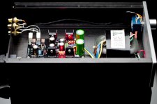

Very nice and you are welcome. This is a gen1 single layer Hypnotize board though. Not a Mezmerize.
What are the dissipation requirements of the current setting resistor at 3r3?
Thanks,
Greg
Greg,
If you look at http://www.diyaudio.com/forums/analog-line-level/171715-salas-hotrodded-blue-dcb1-build-180.html .... Post 1795.
Those sinks were at 55 Degrees with 3R0. I went back to 10R. I might just try 4R7 in the future.
Andy
Last edited:
Offset Problem
Hello,
I´ve finished my Mezmerize DCB1.
The measurements are:
- 9,8V
+10,31V
DC-Offset
R -2,2mV
L -37,1mV 😕
Every part is matched and measured before soldering (the LED sets and SK170
are from Ed).
What could be the reason for this bad offset?
Do I have to change some LED´s.

Thanks for your help
Andreas
Hello,
I´ve finished my Mezmerize DCB1.
The measurements are:
- 9,8V
+10,31V
DC-Offset
R -2,2mV
L -37,1mV 😕
Every part is matched and measured before soldering (the LED sets and SK170
are from Ed).
What could be the reason for this bad offset?
Do I have to change some LED´s.
Thanks for your help
Andreas
Have you got the 2SK170s with their correct matched pair?
Don't connect it to an amp just yet.
Measure the voltage across each LED to see if we can't match the rails a bit better. The absolute voltage isn't that important but V+ should be within 100mV (or better) of V-.
Don't connect it to an amp just yet.
Measure the voltage across each LED to see if we can't match the rails a bit better. The absolute voltage isn't that important but V+ should be within 100mV (or better) of V-.
- Home
- Amplifiers
- Pass Labs
- Mezmerize DCB1 Building Thread