I'm sorry to have dragged you to this problem Salas. Just let me know where to concentrate on working and you can let me go. I guess I just have to replace each component in that area where the fault could be lurking at. I am sure to replace the resistors around the relay as I ordered them already from Mouser. Should I work on the left side of the Mosfets (except maybe the relays)?
Thanks a lot Salas for putting up with me.
Eric
Thanks a lot Salas for putting up with me.
Eric
Also see to have no flux residue around the four JFETS joints. Clean well with alcohol. Isopropyl or other highly pure.
I'm sorry to have dragged you to this problem Salas. Just let me know where to concentrate on working and you can let me go. I guess I just have to replace each component in that area where the fault could be lurking at. I am sure to replace the resistors around the relay as I ordered them already from Mouser. Should I work on the left side of the Mosfets (except maybe the relays)?
Thanks a lot Salas for putting up with me.
Eric
Its very high persistent offset that I haven't seen before, on the other hand I haven't seen a DCB1 build with a problem that it did not work in the end. Concentrate on IDSS re-matching and a clean board for now.
power for muses-attenuator?
Hello again!
I just can't stop looking for reasons not to be finished with the DCB1 😀
So right now I have those muses-boards from meldano, which seem to be very good.
(how) can I draw the power from the DCB1-Board?
The muses chip / board needs to be powered (+-15V), but I haven't yet found more specifics.
Muses' thread here
Documentation here
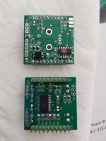
The image has been taken from another thread for reference. I hope it's ok without having notified the owner...
Hello again!
I just can't stop looking for reasons not to be finished with the DCB1 😀
So right now I have those muses-boards from meldano, which seem to be very good.
(how) can I draw the power from the DCB1-Board?
The muses chip / board needs to be powered (+-15V), but I haven't yet found more specifics.
Muses' thread here
Documentation here
The image has been taken from another thread for reference. I hope it's ok without having notified the owner...
Attachments
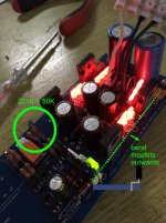
Because there is more than 15-0-15V DC across the DCB1's reservoir capacitors we can tap from there to feed some Low Drop Out (LDO) chips regulated board for +/-15V output.
Because there is more than 15-0-15V DC across the DCB1's reservoir capacitors we can tap from there to feed some Low Drop Out (LDO) chips regulated board for +/-15V output.
Thank you, Salas!
This was most probably already mentioned here, will search for it (now that I have the correct terms to look for [emoji2960])
I‘ll „probably“ will have to come back for further instructions, though!
Best
David
@myleftear, see if the TI LM2990-15 and LM2940-15 will work for you. I have been looking for a way to get +/-12V out of a dual 12.7V (9V CT xformer). If you look at the chart, it specs minimum input voltage of 16.75V for the 15V part (1.75V drop) but in the opening statement it says if you stay below 1A, typical drop is below 0.5V for the + reg and 0.6V for the - reg.
LM2990
LM2940
LM2990
LM2940
Hi Salas!
Problem solved. you were right all along. Those 4 JFETS were the culprit. Their IDSSs were matched by me prior to assembly but I guess Ebay is not a good source for these critical parts. I just got a quad of matched LSK170s from DIYAUDIO, installed them and the DC offset are now 2.0mV and 2.6mV! I saw that the resistors on the signal are are 5% tolerance. Are they critical to be 1% because I ordered 1%s from Mouser and awaiting their arrival.
Again BIG THANKS Salas!
Nothing much, you are welcome. They should have been somewhat defective. Congratulations for fixing it. No, not critical for exact values those signal related resistors. General purpose parts like Dale CMF series and KOA Speer MF series at 100ppm, or at even less when available, are good neutral picks. If you already use some good quality type don't hasten to replace it. At least not before you listen enough to establish a tonal reference for comparison.
Hi everybody,
yesterday I discovered my commercial AM-AUDIO 04f preamp has a faulty channel. It is more than 30 years old and I am not sure to repair it (it failed already 3 years ago).
I thought I could assemble a DCB1 Mesmerize and I started to prepare the BOMS.
Some questions:
1) PNP transistor BC560CTA is obsolete. Online service proposed me the BC556CTA (BC550CTA ON SEMICONDUCTOR (FAIRCHILD) - Transistor: NPN | bipolare; 45V; 0,1A; 500mW; TO92 | TME - Componenti elettronici). Is it fine?
2) I did not find 221R and 221k resistors. I listed 220R and 221k (1% 1W 50ppm) instead. I believe is fine, am I right?
3) As I was expecting I did not find JFETS on Mouser, Digikey, TME...Is there anybody who could help me in Europe to obtain 4 matched and 6 unmatched?
4) Regarding the enclosure: which HiFi2000 Galaxy would suite according to DIYers experience?
5) This would be my first attempt to build a preamp without a guideline or step by step instruction...the other projects I managed to complete where based on kits and some manuals. Here there is this massive thread where posing questions. This is great but also a little bit scary. Many people are referring to measurements, DC offset...but argh, where are those steps described for some newbie like me?
6) concerning the volume pot I listed this one:
KKA2531S28 Precision Electronics Corporation | Potenziometri, resistori variabili | DigiKey
It is 25k but I read that should be fine. It is for wall installation which is fine since I do want to use a long shaft and in my plan I would like to use a rotary switch to deviate the input signal to two output connectors before the pot. Like "tape out" selector which was common in the past. The idea is to leave the option to connect a headphone amp without having the signal going through the pot. Doe it make any sense?
Thanks for the help.
Glicioto (from ITALY)
I am very sorry for a double message.
I forgot to ask an important thing. Are there kits with selected parts available for shipping to Italy?
Many Thanks
Glicioto
I forgot to ask an important thing. Are there kits with selected parts available for shipping to Italy?
Many Thanks
Glicioto
1) Yes BC556C instead of BC560C its fine (the link is wrong, points to BC550C NPN).
2) Same thing 220R & 220K are also fine.
3) DiyAudio Store ships parts from USA other than chassis that ship from ITALY. But better wait and have LSK170 JFETs you can trust. As seen in recent posts even some correct looking Toshiba JFETs from Ebay proved defective.
4) Yes very popular Italian boxes, I have seen many reported builds in them. Medium width 2U size is enough.
5) A quick essential build tips and BOM guide can be found there: Mezmerize B1 Buffer – diyAudio Store
6) Has good reputation as a pot. Look in Mouser also because it ships parts to European customers from Italy I think. I don't know if Digikey does the same.
Tape out (rec out) taking off before the pot makes sense. Put 100R resistors in line to such an output for some isolation.
About selected parts needed like the JFETs quad and not selected parts like the rest of JFETs (must simply be IDSS grade A or B) ask at the DiyAudio Store. There are no full kits.
... Put 100R resistors in line to such an output for some isolation.
Thanks Salas,
With the sentence quoted above you mean to have two 100ohm resistors connected to left and right RCA positive plugs? Will not decrease the output level too much? Maybe a silly question sorry.
In any case which power rating should I look for?
A diode will do the same job? If yes which kind and which specs?
thank you
Glicioto
Yes I mean have two 100ohm resistors connected to left and right RCA positive plugs of "tape out".
They make essentially no drop because the input impedance of the equipment to be connected on "tape out" is much larger than them. Power rating any, no heat. Their job is to damp possible interference and the unavoidable extra interconnects capacitance in the through loop.
No a diode will not do the same job. It would rectify the signal to bad effect. All negative going parts of signal waveform would be cut.
3) As I was expecting I did not find JFETS on Mouser, Digikey, TME...Is there anybody who could help me in Europe to obtain 4 matched and 6 unmatched?
glicioto
I went through the same path as you do.
Found my JFETS here: Studio Electronics in Burbank, California[title]=Y&s[short_desc]=Y&s[full_desc]=Y&s[sku]=Y&s[match]=all&s[cid]=0&s[search]=2SK170BL
unmatched (single pieces) JFETS go for $4, a matched quad costs $20 (= $5/each)
They cost about the half of diyaudiostore's offering. But the match was just so-so.
It worked but wasn't on the marvellous side...
happy soldering!
david
Correct, what the shop does not mention it is the price for unmatched parts. I imagine it should be lower than 7$ for each one. I wrote them on the shop support forum. Let's see what will they answer.LSK170 grade B IDSS quad +/-0.1mA match says $29 at the shop.
LSK170 grade B IDSS quad +/-0.1mA match says $29 at the shop.
Never trust a dilettante in a hurry [emoji849]
Correct, what the shop does not mention it is the price for unmatched parts. I imagine it should be lower than 7$ for each one. I wrote them on the shop support forum. Let's see what will they answer.
I don't know if the shop really offers non matched units. They also have a contact email in the about us section of the diyA store.
I thought I could assemble a DCB1 Mesmerize and I started to prepare the BOMS.
4) Regarding the enclosure: which HiFi2000 Galaxy would suite according to DIYers experience?
5) This would be my first attempt to build a preamp without a guideline or step by step instruction...the other projects I managed to complete where based on kits and some manuals. Here there is this massive thread where posing questions. This is great but also a little bit scary. Many people are referring to measurements, DC offset...but argh, where are those steps described for some newbie like me?
6) concerning the volume pot I listed this one:
KKA2531S28 Precision Electronics Corporation | Potenziometri, resistori variabili | DigiKey
It is 25k but I read that should be fine.
Glicioto (from ITALY)
I chime in a bit late ( and I'm not very experienced in electronics but I built a DCB1 🙂 )
Chassis: I got myself a galaxy 3U 230 x 230 — it is too high, depending on your transformer (and other additional stuff), you could easily go with a 2U 230 x 230... If you'd wand to go as slim as possible, you could "kink" 90° the big capacitors, and use some heatsinks less high but with more width, and stuff it into a 1U!
Pot: As Salas told me, you may want/need to adjust the 221K resistors for the 25K Pot (270K for the 1:10 Rate... Salas gave me the hint... I soldered a second Resistor in series to get there...)
Measurements: Don't worry, it is possible. Even I could do it 🙄. (Ask again when you're there...)
Additional: If you're going the strict BOM-route with the Fischer-heatsinks, be aware that those are rather big. But you'll need them if you "hot-rod" the DCB... I'd recommend to bend the MOSFETS in a "zig-zag" to get them as close to the board's border as possible...
Also, I'd recommend to solder the connectors to/from the transformator under the board. There's not much space for wires on the upside.
Good luck, much fun!
DCB is a absolute great little gem!
Attachments
Last edited:
- Home
- Amplifiers
- Pass Labs
- Mezmerize DCB1 Building Thread