Thanks Salas!!
I was start to worry a little.
The longest interconnect will be 1 meter...most
Thanks...
I was start to worry a little.
The longest interconnect will be 1 meter...most
Thanks...
Thanks Salas. Your promptness is amazing. I guess your suggestion point in using a switch after the alps potentiometer. Sounds wise.@ Gli
Its a good idea to redirect the signal with a switch so to isolate the two circuits.
The Mezmerize 2018-19 notes refer to fuses rating for 50VA own transformer.
https://cdn.shopify.com/s/files/1/1006/5046/files/Mez_TYA_018_BOM_Notes_Rev.pdf?70
Mezmerize FET's
hi just finishing off my Mezmerize b1 build and got to the main 4 fets just how good a match is needed ?
I have used 12v 100R resistor test and got the following results 7.55-7.66-7.54-7.56 are these good enough ?
or do i need them to be closer
hi just finishing off my Mezmerize b1 build and got to the main 4 fets just how good a match is needed ?
I have used 12v 100R resistor test and got the following results 7.55-7.66-7.54-7.56 are these good enough ?
or do i need them to be closer
just powered the board up without the 4 fets and got
+9.695v & -9.682v
and across the 2x 68R -2.033v & +1.906v
Is this ok ?
+9.695v & -9.682v
and across the 2x 68R -2.033v & +1.906v
Is this ok ?
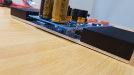
soldered the 4 fets 7.46 7.44 7.49 7.55
rail voltages are +9.77v -9.74v
voltage across 2x 68R +1.957v -2.042v
dc offset 001.5v 000.7v
looks like all is well
 20200213_105033 by glenn jarrett, on Flickr
rail voltages are +9.77v -9.74v
voltage across 2x 68R +1.957v -2.042v
dc offset 001.5v 000.7v
looks like all is well
20200213_105033 by glenn jarrett, on FlickrYou mean 1.5mV & 0.7mV DC offsets? If so, things are very good overall. Nice picture by the way.
Maybe it's the photo, however one of the irfp9240's could perhaps do with a bit more solder? (bottom left, middle pin)
Last edited:

Very nice! What did you use for the rectifier diodes?
Also, though I haven't mounted my irfp9240's yet, I have assumed until seeing your photo that they would be mounted the opposite way given the drawing on the PCB. Glad I saw your photo!
Also, though I haven't mounted my irfp9240's yet, I have assumed until seeing your photo that they would be mounted the opposite way given the drawing on the PCB. Glad I saw your photo!
Maybe it's the photo, however one of the irfp9240's could perhaps do with a bit more solder? (bottom left, middle pin)
Indeed. Maybe there is a fillet underside though. But he better touch it up with a bit of solder on the top side too.
I lost that pad moving the irfp's from top to bottom but the underside is good
BYW29E-200 diodes i think
BYW29E-200 diodes i think
Just removed the 2x 68r per side (34R)
and replaced with 1x 10R per side
was getting 2.042v & 1.957v across the 2x 68R per side but only getting 1.739v & 1.628v with the 10R resistors is this ok as i was expecting more voltage with the 10R per side
and replaced with 1x 10R per side
was getting 2.042v & 1.957v across the 2x 68R per side but only getting 1.739v & 1.628v with the 10R resistors is this ok as i was expecting more voltage with the 10R per side
Its counter-intuitive but its right. Has to do with increased VGS (due to more current) reaching nearer to the three LEDS combined VF. That VF-VGS difference is what you measure across the setting resistor. Despite ~0.3V Vref loss you went from 60mA to 163-174mA now.
seeing i have adequate cooling should i lower the resistors to 3R for more mA or would there be no improvement
i also only have a 50va 2 x 15v transformer
regards Glenn
i also only have a 50va 2 x 15v transformer
regards Glenn
Most builders were historically happy enough where you now stand as it was discernibly better than with 60mA when further on it just gets gradually better. That was with bigger transformer and Hypnotize single input version which had more reservoirs. With your transformer and a Mezmerize try down to 5 Ohm I would say and judge for yourself. Piggy back another 10 Ohm on each Rset is the easy way. Monitor your rectifier diodes temperature also.
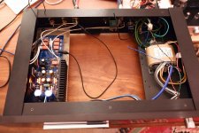
Hi -- I'm also building the Mez B1, and just got to listen to music through it for the first time today! Beautiful.
Here's a quick picture of where I got today. As you can see, there's space for an internal DAC streamer which will go in there next, as soon as I get the PSU boards from Teabag. I'll post more/better pictures when I'm done.
I could not have gotten this far without this forum and all your advice, so thank you all for that, and thank you to Salas for designing this beautiful piece.
Attachments
- Home
- The diyAudio Store
- Mezmerize B1 Buffer Preamp