The most important figure of merit for a MOSFET to be used as source follower driven by a high impedance triode is the MOSFET's Crss (Reverse transfer capacitance). Fortunately, it's not that critical unless you try to drive a MOSFET with a 12AX7 set to a plate current of only 500uA or so. You'd like to see the MOSFET's Crss be less than 10pF (the lower the better).
IRFBC40LC - Crss = 15pF
IRF840 - Crss = 8pF (surprisingly good)
FQPF2N60C - Crss = 5.6pF
IRF820 - Crss = 37pF (that's not so good!)
IRF710 - Crss = 6.3pF
ZVN0545A - Crss = 4pF
There are many more to choose from...
IRFBC40LC - Crss = 15pF
IRF840 - Crss = 8pF (surprisingly good)
FQPF2N60C - Crss = 5.6pF
IRF820 - Crss = 37pF (that's not so good!)
IRF710 - Crss = 6.3pF
ZVN0545A - Crss = 4pF
There are many more to choose from...
Ah, ok, thanks! Not so optimum as a replacement then, but ought to work in this situation.
Wondering how others are coming along with their boards? I have a power supply and most of the RIAA board ready now, missing some hardware but able to do some testing soon. The power supply is tested and it seems to stick at around 289V, which is the same as the simulation. (Anyone interested in that?).
I found the PCB was not so forgiving of errors. I wanted to swap some electrolytics that had the wrong raster to ones that fitted right and managed to lift a trace. The tight hole and the ground plane conspired to make it hard to get the heat to flow enough to just lift the part. Otherwise it has been a very Zen experience, trying different combinations of top and bottom placement of parts. Now I need to plan the enclosures.
The hard part is going to be remembering which box the tubes are in ...
Last edited:
Hallo, I am interested too for a pair of pcbs.created a template. If there are enough interested, I can have a few circuit boards made.
View attachment 1197233View attachment 1197232
Thinking about future versions of this project, wondering is anyone has see @v4lve lover 's boards that provide 6.3VDC at 2A from a 6.3VAC supply.
Unless one uses different transformers, or has a custom one provided, the requirement for a 9V secondary is a bit of a restriction. Would it be worth incorporating this type of solution on the PSU board?
Unless one uses different transformers, or has a custom one provided, the requirement for a 9V secondary is a bit of a restriction. Would it be worth incorporating this type of solution on the PSU board?


Digikey has 1 week of December so not totally unobtanium. That would be a great little board for lots of little preamps or headphone amp projects!
if it doesn't necessarily have to be Pb-Free and with a PCB modification there are several to choose from 😎
they are also available on ebay / aliexpress (I'm not a friend of mouser, digikey e.g.)


they are also available on ebay / aliexpress (I'm not a friend of mouser, digikey e.g.)
What about BS107G instead of that ZVN0545A? It may also be obsolete, but in my case it's a good option, I already have few pcs. from an old project. I the reverse transfer capacitance is the only important matter, in this case datasheet says it's 6pF. At least the OnSemi version...
BS107G maximum drain-source voltage is 200V, which could be a problem at turn on.
ZVN0545A max drain-source voltage is 450V.
That's a big difference.
ZVN0545A max drain-source voltage is 450V.
That's a big difference.
As I think about future versions of this project, I wonder if it would make sense to integrate such a solution on the power supply board?
I have made the (modified) Gerber data available (for the 6.3v part of this circuit) for download here in this thread 😉
6.3VAC to 6.3VDC LDO supplies MIC5156 based tube amp upgrade
Hi SnapperIt could then look like this, MIC5156YN is just another circuit that is not available anywhere!
View attachment 1235687
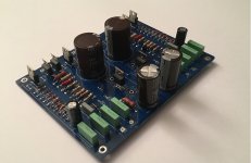
Has the circuit board in the attached picture been tested? Does it work? I need a compact circuit like this. Both low voltage and high dc voltage together. I would be happy if you share it.
I am going to order some toroids from Toroidy. I have a couple of other projects on hold for power transformers and I like being able to hide the power transformer under the chassis, and toroids are nice and slim. I.e. the postage is a sunk cost, so the Toroidy price is comparable with the prices @snapper quoted.
It is a custom wind. This is the quote, anyone else interested if I tell them there will be more takers? (Maybe the price will go down for other people).
Custom made Audio Grade transformer TS30VA PRI: 230V SEC:
SEC I: 235V (40mA)
SECII: 0 - 6,3 - 9V (2A)
price: 60,30 EUR / pc (VAT tax included)
Is anyone building this with the 10H choke? If so what resistance are you using and how does that impact B+? I saw Marc originally tested with a 10R resistor and he said he heard little difference. Anyone else tried that?
@OldHector : "This is the quote, anyone else interested if I tell them there will be more takers?"
count me for same Toroidy transformer and let me known how to procede if you made the order. Thank you.
count me for same Toroidy transformer and let me known how to procede if you made the order. Thank you.
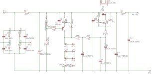
It seems the same circuit I done years ago and published also here
The main issue is the use of 100 uF after the possible inductance
Take a care with ss rectifier and the inrush current
I suggest to use a 100 ohm resistor
With this topology the ripple is dead
Walter
If FQPF2N60C is a good option, then FQP2N60C may be also good, and it's available on Mouser:
https://ro.mouser.com/ProductDetail/onsemi-Fairchild/FQP2N60C?qs=UMEuL5FsraCCnxush%2BstnA==
The only "drawback" - if one could call this so, is the unisolated case...but also IRF840 is the same package...
https://ro.mouser.com/ProductDetail/onsemi-Fairchild/FQP2N60C?qs=UMEuL5FsraCCnxush%2BstnA==
The only "drawback" - if one could call this so, is the unisolated case...but also IRF840 is the same package...
- Home
- Amplifiers
- Tubes / Valves
- Merlin RIAA Preamp