I am more worried about how the different Cga and miller/gain will effect the RIAA accuracy.compare the dates !
because of the different heating wiring set jumpers as for 6N1P.
the PCC88 have 3.8V heating because a series resistor would have to be in as with the PC97/900.
not much can break, but I doubt if the whole thing works like it does with ECC82.
Still, thank's for the tip on 6N1P setting.
I must admit to getting a bit confused when referring to voltage's for "P" type tubes like PC900 and PCC88.
To the best of my knowledge the "P" means 300mA constant current and then the voltages would be whatever they would be.
For example a late Philips PCC88 datasheet indicate that the PCC88 will develop 7.6 volt across the heater at 300mA while older datasheet indicate 7 volt for same current. If I go with PCC88 and can easily modify the PCB to series connect all tubes I will use 300mA constant current for heating instead of 6.3 volt.
also just seen:
the data sheets all indicate 7 or 7.6V heating! 3.8V would only work if pin9 was internally connected to
the middle of the filaments and you bridge Pin4/5 similarly 6.3V operation with e.g. ECC82.
So if you have PCC88 available, measure it, otherwise the 6N1P setting is useless!
https://patric-sokoll.de/Röhrenmuseum/Datenbank/RöhrenTypen/PCC88.html
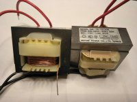
free heating transformer: you can find heaps of 12V halogen lamps at the recycling center,
as they are usually replaced by energy-saving led technology.
the transformers installed in it can be used very well as heating transformers by unwinding the secondary side.
but be careful, connect a load from time to time, otherwise you can easily unwind too much! 😎

as they are usually replaced by energy-saving led technology.
the transformers installed in it can be used very well as heating transformers by unwinding the secondary side.
but be careful, connect a load from time to time, otherwise you can easily unwind too much! 😎

Some parts arrived from Mouser last week, and I started to look at populating a couple of boards. I ordered some silly 47uF/400V caps that are 1cm wide and 4cm tall since I had not looked at all the details closely enough. and the raster of the 220uF/16V caps I have is 5mm, but is 3.5mm on the board, so they are not flush.
I had some bits that I had lying around that I wanted to use up, such as 1/4W 1meg resistors, so I simulated the circuit to check dissipations so I could get rid of a few bits like that.
I had not appreciated the total parts count for both boards until I started work on these! It is quite a crowded board.
So far the only issue I have come across is the holes on the PCB are too small for the 5W zeners, used to clamp the 330V on the PSU. Maybe it was the zeners I bought, but they will need an improvised solution to be used. I am thinking the wattage my be greater than needed, but I am yet to check that.
The C0G MLCC caps for the RIAA equalisation look to be a good choice, and they all have a raster of 5mm, but they had longish leads so not an issue.
There is a 15mm raster 0.1uf 400V cap on- the PSU board, and 10mm ones on the phono board, perhaps they could be the same in the next version?
I have some 470uF 400V caps that fit on the PSU board, so will probably use them instead of the 330uF ones, unless there is a good reason not to?
I have a lot of very nice NOS 7 pin sockets, but the leads are just too wide to fit in the holes on the board. Perhaps the holes for the sockets could be bigger in a future revision? It will be painful to order some of those because I have so many, so perhaps I improvise here as well.
I am not aware that such diodes are installed in the RIAA power supply!"for the 5W zeners"
Correct, I overlooked😱
5W z-diodes have legs with a diameter of 0.94-1.09mm, so a 1mm hole could be tight !
I also think 5W is oversized, I know of several other identical high-voltage power supply circuits
and they all have max. 2W Zener diodes of type ZY installed in this place.
5W z-diodes have legs with a diameter of 0.94-1.09mm, so a 1mm hole could be tight !
I also think 5W is oversized, I know of several other identical high-voltage power supply circuits
and they all have max. 2W Zener diodes of type ZY installed in this place.
Last edited:
It will probably be difficult to design PCBs that fit all the NOS components that people still have in their inventory. If you tell me special requests before production begins, I will be happy to take them into account 😉I have a lot of very nice NOS 7 pin sockets, but the leads are just too wide to fit in the holes on the board.
The ones I ordered have 1.2mm legs, but I have other 200v 5W zeners with narrower legs. I think I will solve it with a little daughter board. I wanted to simulate the circuit to get a value for the dissipation. It does seem to be a bit overspecced.
Now I see I have some SMD IRF840 MOSFETs. Clearly there was a critical caffeine imbalance when I sent off my order :-/
@Ryssen What did you use for a choke?
Now I see I have some SMD IRF840 MOSFETs. Clearly there was a critical caffeine imbalance when I sent off my order :-/
@Ryssen What did you use for a choke?
I ordered one of this, https://www.aliexpress.com/item/100....order_list.order_list_main.16.21ef1802FQckch
have not used it yet. 10H/25mA
have not used it yet. 10H/25mA
Too complex, since the conductor tracks for the Zener diodes only run on the back of the board, no through-plating is required there, so simply drill out with 1.3mm.The ones I ordered have 1.2mm legs, but I have other 200v 5W zeners with narrower legs. I think I will solve it with a little daughter board.
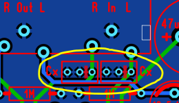
There is provision for two small capacitors in parallel with the RIAA input and the 47K load impedance. I tried to get an idea of what to shoot for for those, and I think 200pF came up a few times.
It is meant to be optimised for the cartridge and I suppose that will be for an Ortofon OM cartridge, although I am looking for a general option for other turntables. I looked up the cartridge data on the Ortofon site, and 200-500pF is recommended.
Wondering if there is an optimum choice for this capacitor?
Yes, you are right! Good to have a place to find the voice of reason!Too complex, since the conductor tracks for the Zener diodes only run on the back of the board, no through-plating is required there, so simply drill out with 1.3mm.
The 100V ones will go into my ever expanding parts bin, and I will order the 75V as mentioned by @Ryssen . They can go in the order for IRF840's, with leads this time :-/
For input capacitor loading a cart basically you should know the following :
Capacitance of the cables / tonearm + IC + rca plug
Capacitance of the input stage + strays from socket, rca connectors and cable from rca to pcb input
Cart manufacturer recommendation
P.S. My choice for this are Wima FKP2 capacitors
Capacitance of the cables / tonearm + IC + rca plug
Capacitance of the input stage + strays from socket, rca connectors and cable from rca to pcb input
Cart manufacturer recommendation
P.S. My choice for this are Wima FKP2 capacitors
Would it be a worthwhile change to make the pin spacing 7.5mm for the 47uF 400VDC caps? That makes it easier to find less tall caps, down to 30mm. Possibly the 220uF 16VDC caps could have 5mm instead of 3.5mm as well.
And just a thought because I don't know all the complexities of working with a PCB, move the PC97/900 heater supply onto the PSU board, 2 keep those heat generating resistors away from the RIAA stage, and simplify the switching of tubes on the RIAA board.
And just a thought because I don't know all the complexities of working with a PCB, move the PC97/900 heater supply onto the PSU board, 2 keep those heat generating resistors away from the RIAA stage, and simplify the switching of tubes on the RIAA board.
OK, 7.5mm for the 47µF 400V has been changed,
new 220uF 16V only have 2.5mm pin spacing,
if that bothers the resistors you can use EC97 with 6.3V heater and replace the 3W resistors with wire bridges!
In addition, the PC97/900 only have a higher current in the short warm-up phase, so 2W resistors are completely sufficient.
RV PC900 2.4V 0.3A, P=0.72W
RV PC97 1.8V 0.3A, P=0.54W
- Home
- Amplifiers
- Tubes / Valves
- Merlin RIAA Preamp
