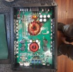
I removed all of the outputs and the rectifiers and replaced all of the 3205's on one side of the PS. Pin 16 of the 594 is driving pin 3 high. I grounded pin 3 and the power supply runs fine without any problems.
Some of these amps have a protection circuit that will shut the driver IC down if it doesn't see rail voltage. You can either find the protection circuit transistors or install the rectifiers.
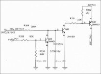
There are variations but the attached is one version. You'd remove/lift Q87.
There are variations but the attached is one version. You'd remove/lift Q87.
Attachments
Last edited:
Thanks Perry! I installed the rectifiers and it runs with no problem. Drawing .8 Amps. Working on these things can be humbling.
Feel free to ask questions.
Wait until you get a Brazilian type amp that uses an MCU to control everything and all coding is proprietary... and many replacements must come from Brazil... and they do fail. To make them even more fun, many deface the semiconductors and to make it just a bit more fun, the over-current protection is (supposed to be) matched specifically to the output FETs. Failure to make the calculations and circuit mods will not allow the over-current protection to function. They also have two different protection circuits per driver IC that require different calculations. AND that's virtually all that's being sold because they're cheap and that's the most important aspect of an amplifier for many people. For the larger amps (power rating), they can take 900+ amps of current to run up to full power.
What do you normally repair?
I don't have a select line of products that I repair. I am retired and just enjoy the challenges. I work on a lot of flat screen TVs, cordless power tools, stage monitors, appliances, laptops and other things. Car amplifiers and TVs for the most part.
On the outputs for this amp, it has IRF640Ns. One of them on each side was blown. I moved one from the other bank and removed the rest in that bank. I don't have any IRF640Ns. Can I safely use IRF640s?
If this amp is like the diagram that was posted, I've seen these using both. Make sure that you don't mix old and new and that the parallel FETs are from the same batch.
If the 640s run hotter than the 640Ns, it may be worth it to order the originals.
If the 640s run hotter than the 640Ns, it may be worth it to order the originals.
The 640Ns are a bit better suited for switching circuits than the older 640s. As stated, both are used in various amps. These will likely be reliable but, as (virtually) always, I suggest using the original part number.
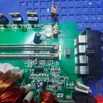
Trying to identify this output board. U3 is a dual op-amp. I have been unable to identify U2. The 14-pin IC from what I can gather is a quad 2 input NAND gate. I don't think I have ran across this and I can't seem to locate it in the repair tutorial. I seem to be missing drive on one side of the amp.

JRC2068 and LM6172. These vary quite a bit from various build houses.
If you have the tutorial, on the Type 4 page, perform a ctrl-f search for:
The letters on the diagram
There is a white diagram under that that shows the basic circuit. Again, not all are identical but it gives you the basic layout.
Do you have two output signals from the board? That will give you a good idea as to where the problem is without replacing parts.
I guess I was just too scared to turn the amps up on my limiter.This amp is pulling 9 amps with no input signal or load. The scope traces seem fine. Is this normal?


You need to use your scope in differential mode. Do you know how to do that?
9 amps is not normal. Are any of the FETs heating up? If so, which ones?
9 amps is not normal. Are any of the FETs heating up? If so, which ones?
I have a set of differential probes. Where do I reference for the high and low sides? The rail voltages? The IRF640s were heating up faster than the IRF640Ns. I have it in the heat sink now, but that side with the IRF640s still seems to be running warmer. Do you think using a different gate resistor would help? It has 22 ohm resistors in it.
DC coupling
5v/div
5us
negative probe on the FET source terminal
positive probe on the FET gate
22 ohms is typically higher than is used.
5v/div
5us
negative probe on the FET source terminal
positive probe on the FET gate
22 ohms is typically higher than is used.
- Home
- General Interest
- Car Audio
- Memphis SRX1200D.1 protection circuit