
I completely understand the o-scope is very limited. Is there anything else I can do to track this overheating issue? Other than buying a capable o-scope.
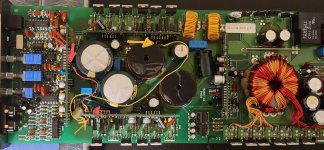
Is there a small jumper wire from the audio PWM board to the driver board on the side that's heating up?
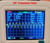
I think the white wire is the drive signal. You can confirm.
Jumping that wire from point to point on the bottom of the board (electrically parallel with the top jumper) may help. On one amp, I used a 22g wire and it helped.
Confirm that you read 0 ohms between the two points before adding the jumper, if you try this.
Jumping that wire from point to point on the bottom of the board (electrically parallel with the top jumper) may help. On one amp, I used a 22g wire and it helped.
Confirm that you read 0 ohms between the two points before adding the jumper, if you try this.
I'll try this out tomorrow.
To clarify when you say to jump the wire on the bottom "electrically parallel with the top jumper" are you saying to run the wire along the same path as the top jumper wire?
Or can I just jump the wire following the shortest path?
I have some 22awg enameled magnet wire. Will this suffice?
To clarify when you say to jump the wire on the bottom "electrically parallel with the top jumper" are you saying to run the wire along the same path as the top jumper wire?
Or can I just jump the wire following the shortest path?
I have some 22awg enameled magnet wire. Will this suffice?
I'd use normal wire (PVC type insulation). I only mentioned the gauge so you'd know the approximate size you need.
Run the short route. Not physically parallel.
Run the short route. Not physically parallel.
Hi Perry I added the extra jumper cable and still have overheating.
Question regarding the op-driver boards. Should the components on these boards be identical on both boards?
I can see some aluminum caps and certain transistors are not the same. I understand that when replacing these board transistors, they should be done on both boards rather than replacing once side.
Could this be the cause for the overheating? I'll start logging the components and report back the differences.
Are the part numbers on the board the same? I've seen 2 different boards used.
Didn't you say that the same outputs heated up regardless of the driver board used?
Didn't you say that the same outputs heated up regardless of the driver board used?
Correct regardless of the board the same side Q211-Q216 overheats.
Part number on the on the OP-drivers are the same with only the 0405 and 0407 marking being different.
Audio PWM Driver and PS-PWM Driver are different.
Pics attached.
Part number on the on the OP-drivers are the same with only the 0405 and 0407 marking being different.
Audio PWM Driver and PS-PWM Driver are different.
Pics attached.
Attachments
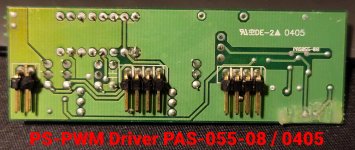
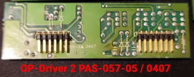
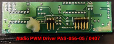

They are two different boards.
Where did you buy the FETs that you used in the output section?
Are the FETs on both the heating and the cool sides from the same source?
Are the gate resistors within tolerance?
Where did you buy the FETs that you used in the output section?
Are the FETs on both the heating and the cool sides from the same source?
Are the gate resistors within tolerance?
Fets were purchased thru Amazon all the same batch.
Although now I believe the gate resistors may be out of spec.
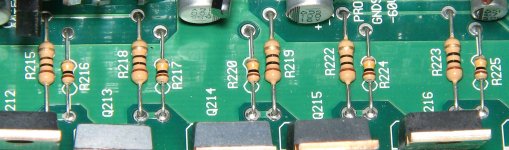
Correct me if I'm wrong with the color coding.
Resistor 1=Red/Blk/Brown/Gold =200ohms
DMM reading= 10ohms
Resistor 2=Red/Brown/ Yellow/Gold=210k ohms
DMM=50k ohms
Although now I believe the gate resistors may be out of spec.
Correct me if I'm wrong with the color coding.
Resistor 1=Red/Blk/Brown/Gold =200ohms
DMM reading= 10ohms
Resistor 2=Red/Brown/ Yellow/Gold=210k ohms
DMM=50k ohms
Attachments

I see
1, 0, 0: brown, black, black (0, no multiplier)
1, 0, 4: brown, black, yellow (4, four zeros)
This is on the IRF640s. The 100ks are essentially in parallel (through the gate resistors). Two 100k resistors in parallel will read 50k.
The BP1200 is a similar design and shows the resistors.
http://www.bcae1.com/temp/bp1200p1_sm.pdf
The attached image is from a different memphis 1000. The resistors have a bit better paint job.
Attachments
Ok so the resistors are in spec.
Question about the transistors.
When probing the 9640 with the DMM in diode mode.
Positive on Drain, Negative on Source = ~0.407
640= + on source, - on drain = ~0.701
This is on both banks
Are the 9640's out of spec?
Question about the transistors.
When probing the 9640 with the DMM in diode mode.
Positive on Drain, Negative on Source = ~0.407
640= + on source, - on drain = ~0.701
This is on both banks
Are the 9640's out of spec?
It's not reliable to check the FETs in the circuit.
Tolerance isn't really a test for FETs.
How do the readings compare with the ones of the same part number that you pulled from the amp (out of the circuit)?
Tolerance isn't really a test for FETs.
How do the readings compare with the ones of the same part number that you pulled from the amp (out of the circuit)?
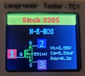
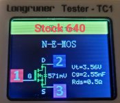
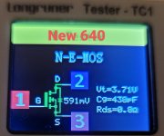
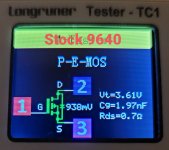
Here's are some pics of the readings for the mosfets new and stock.
The new 9640 and 640 seem to be out of spec vs the stock.
3205's look to be within spec of stock.
I was able to determine one of each stock 3205,9640,640 were shorted or reading as a resistor.
The 640 was reading as a resistor.
The new 9640 and 640 seem to be out of spec vs the stock.
3205's look to be within spec of stock.
I was able to determine one of each stock 3205,9640,640 were shorted or reading as a resistor.
The 640 was reading as a resistor.
Attachments

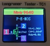
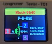
My opinion, this tester is useless.
The resolution is not good enough to tell you much. The Rdson of the 3205 is 0.008. The tester can't read that low. The readings for the rest are far off of what they should be.
If Vt is the gate voltage, they're not using the voltage used by the manufacturer to get the specs.
The resolution is not good enough to tell you much. The Rdson of the 3205 is 0.008. The tester can't read that low. The readings for the rest are far off of what they should be.
If Vt is the gate voltage, they're not using the voltage used by the manufacturer to get the specs.
Hi Perry I understand the meter isn't the best in terms of accuracy.
I've located some replacements for the 9640 and 640.
Mouser has the IRF640NPBF
https://www.mouser.com/ProductDetail/Infineon-IR/IRF640NPBF?qs=9%2BKlkBgLFf3E8kFH1ru13w==
Future has the IRF9640PBF
IRF9640PBF in Tube by Vishay | Mosfets | Future Electronics
Would these be suitable replacements?
Does the difference in Rds(On) in the NPBF and PBF variants of the 640 play any role in deciding which to purchase?
150 mOhms vs 180 mOhms
- Home
- General Interest
- Car Audio
- Memphis 16-MC1000D Ground Short (Newbie 1st Post)