Perry,
Here are the photos as requested.
While testing the Freq was not stable. It would fluctuate between 16.5-17.5Khz.
Should the freq be constant? Or is it common to have fluctuation in freq?
Here are the photos as requested.
While testing the Freq was not stable. It would fluctuate between 16.5-17.5Khz.
Should the freq be constant? Or is it common to have fluctuation in freq?
Attachments
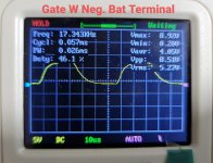

The frequency is too low. I'd expect to be about 25kHz. You may have a bad timing component (Rt or Ct). The differing frequency reading by the scope could be an issue with the scope itself.
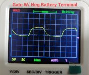
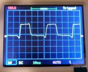
The waveforms look OK.
You can use multiple caps but you can also just move one if you want to check all locations.
The waveforms look OK.
You can use multiple caps but you can also just move one if you want to check all locations.
I've checked the caps and resistor.
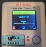
pin 5 Film Cap (2A102J)=1033pf (pic attached)
pin 6 smd resistor(3602)=35.94k ohms (DMM)
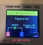
Cap connecting pin1&4
1uF 50v=1049nF(pic attached)
Based on this I assume they are within a safe tolerance.
I'm not quite sure what to make of the 3.1ohm ESR reading on the Cap for Pin1&4.
pin 5 Film Cap (2A102J)=1033pf (pic attached)
pin 6 smd resistor(3602)=35.94k ohms (DMM)
Cap connecting pin1&4
1uF 50v=1049nF(pic attached)
Based on this I assume they are within a safe tolerance.
I'm not quite sure what to make of the 3.1ohm ESR reading on the Cap for Pin1&4.
Attachments
EDIT.
According to the values, the frequency isn't far off if you measured anywhere other than pin 5.
Do these parts look original?
According to the values, the frequency isn't far off if you measured anywhere other than pin 5.
Do these parts look original?
Last edited:
Yes they all seem to be original parts. These same components are used on the op-driver boards as well.
What do you mean by 'the same parts'?
When parts are replaced, the solder doesn't look the same as the flow-soldered parts. Did the solder on these parts look the same as everything else or was it different (more solder and shiny, if hand soldered)?
Where are we at on the repair in general (as far as your questions go)? We've sort of gone in different directions.
As to whether the parts look original. I was using other components as reference. Which is why I mentioned they look the same.(pic attached)
The solder looks dull and untouched on all the boards. The only components I believe to have been replaced were the op-transistors and the addition of the SMD cap between pin 15-16 which I removed.
As for the status of the repair. I was only following along with your guidance. Since much of what you asked to check seems to be within spec. I'll move along and refit the fets and transistors and go from there.(fingers crossed)
I appreciate your help and insight.
Attachments

Last edited:
Hi Perry
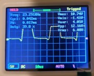
I've refitted the ps-fets and re-soldered the caps on the pulse width driver board. Now the frequency and square wave(hope this is correct?) have changed as of last when I checked with the film caps. It has bumped up to ~24KHz. I hope this is a step in the right direction?
As I'm not versed in how the wave should look can you comment?
Attachments
Going from the cap loaded test to the FETs should not have changed the frequency. Regularly check the frequency through the rest of the repair to see if it changes again.
What's the difference on your scope with the '5v' in a box or without the box?
the waveforms look OK. There's no one 'perfect' waveform. If the waveforms are good with the caps, there is virtually no way that there will be a drive circuit problem.
What's the difference on your scope with the '5v' in a box or without the box?
the waveforms look OK. There's no one 'perfect' waveform. If the waveforms are good with the caps, there is virtually no way that there will be a drive circuit problem.
The box surrounding the 5v is a selection marker/cursor. I don't believe this had any affect on the freq change but I will verify once I get back home.
Also I'll verify that I still have +-60v on the op side before installing the replacement transistors and continue to monitor the freq on the ps-fets. Thanks again
Also I'll verify that I still have +-60v on the op side before installing the replacement transistors and continue to monitor the freq on the ps-fets. Thanks again
I managed to install the replacement transistors. Amp powered up and I was reading a 93KHz on all op-gates with ~52v both +-. The PS-Fets remained at ~24KHz.
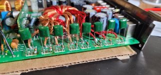
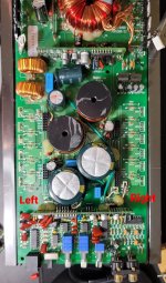
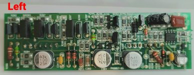
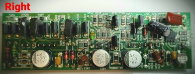
I did notice one bank of transistors(Left side) was running hotter than the other side. For clarity I've marked on the pics attached a left and right side.
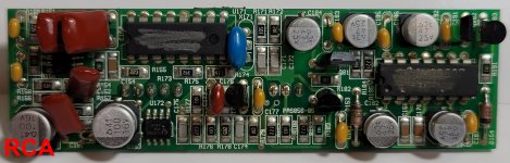
This was all done at idle with no audio signal input(RCA).
I did some process of elimination to determine if the driver was the cause.
I did notice one bank of transistors(Left side) was running hotter than the other side. For clarity I've marked on the pics attached a left and right side.
This was all done at idle with no audio signal input(RCA).
I did some process of elimination to determine if the driver was the cause.
- Initially I swapped the left driver with the right driver. Left bank transistors continued to get hot quickly. Right side remained cool.
- Removed all op-side drivers and driver closest to RCA. All transistors remained cool.
- With both left and right drivers installed individually and in tandem with no RCA side driver. Transistors remained cool.
- Once I installed the RCA driver the Left bank continued to run hot.
Attachments
For #3. I removed the RCA driver board. I did not check the freq. Only checked temp of the transistors with my hand.
I only checked the freq at initial start up when all boards were installed. I did not follow up the freq check thru the process listed above.
I'm guessing I should go ahead and do that again?
I only checked the freq at initial start up when all boards were installed. I did not follow up the freq check thru the process listed above.
I'm guessing I should go ahead and do that again?
To clarify, when you swapped the driver boards, are you saying that the left bank (would prefer circuit designations of these transistors) output transistors got hot or are you saying that the driver transistors on the driver board got hot?
Left bank transistors (Q211-Q216) got hot. Regardless of which driver board was installed.
Both op-driver board transistors did not show any signs of overheating.
Both op-driver board transistors did not show any signs of overheating.
Looking at the rail-rail waveforms on the drains of the output transistors in each bank. are the waveforms the same shape (nice and square) on top and bottom?
- Home
- General Interest
- Car Audio
- Memphis 16-MC1000D Ground Short (Newbie 1st Post)