Hi,
yesterday I tested my ZVS with a BSC25-T1010A CRT Flyback transformer with a jacob ladder style electrode w. and wo blowing in compressed air.
The PS supplying for 16-21V and 8-9A, and depending on the distance and shape of the ladder electrodes a nice blown arc plasma developed.
Funnily the spectacle disturbed an old CRT´s display and shut down a new LG monitor over quite a distance altogether 😆
Seems as if a thorough HF screening is duely advised.
Treating the surface a cable duct prooved that the thing worked. Plain water spread evenly over the surface.
Tested with kind of green Edding pen also. After drying I tried to wipe it off of the cable duct using a cloth and solder resist cleaner.
While it came off completely from the untreated area with some scrubbing it stuck like mud to the proverbial boot on the treated area.
That may answer Daihedz´s Q: "What is it good for?" 😉
This webinar by ellsworth/enercon gives some insights to what the treatment achieves and what is basically going on.
At AIS website one can find reports and videos on DIY gliding arc plasma generators and electrodes ... which is where I got my idea from.
That kind of blown plasma is certainly cold enough for thinnest film PET substrates and allows for treatment of non-plain shaped substrats also.
But I think I´m gonna build me a tubular electrode like Zvon´s asap too .... the smooth plasma and the treatment results just look too promising 😉
jauu
Calvin
Here's one of the protos. Even and odd electrode terminations as well as air path. 3 gaps 1.2 mm total and 4 insulators 3.2 mm total. In order to increase working surface one may do just like that. No picture when operated though.


Hi,
tried today with a aluminum pipe electrode, but w.o much success.
Just a bit of discharge noise and every now and then some serious flashovers.
The BSC25-T1010A CRT Flyback transformer I have contains a couple of Diodes and in #4. no3 Zvon also mentioned to have had bad luck with such transformers.
So I think I need to get me a real ac-transformer.
@alexberg What exactly are we looking at? Do You have a sketch of the device?
jauu
Calvin
Industrially, plasma is described for direct coating of materials. And as now, thanks to this thread, successful plasma treatment seems to get available to the poor... would it be feasible to implement a direct coating plasma process, deploying a "molecular-thin" layer of long-term stable (also under ozone conditions inside an ESL), environmental friendly metal oxyde? A layer maybe also with a narrowly tolerated 200MOhm ... 500MOhm surface resistance?
The electrode itself (eventually made of tin - Zvon mentionned tin oxyde as a coating agent?) might act as a combined doting/coating donator. Or what about a specific "plasma gap addon", such as applying a breeze of suitable metal oxyde powder (tin oxyde again?), priorly evenly dispersed onto the mylar before exposing the PET to the plasma? Thinking of such a plasmatic transfer process, I guess that a voltage symmetric AC plasma might not really work. But what about an AC plasma DC-biased by e.g. some 10% of it's Vss Voltage?
Such a one-pass process with a (near-) perfect result would definitely pay off for the additional care and effort for a neat, DIY-ers kitchen-table plasma system.
Last edited:
Now back to the tube of yours. Basically you need to make a peculiar capacitor. One plate would be sheet metal as per Zvon (first plate) then comes working piece (film) then comes air gap (rather small, few tenths of mm) then comes tube (or insulator with rather high permittivity Al203 in over mentioned thing or you will lose efficiency) and the foil inside the tube (second plate). Bingo #1
In over mentioned case with 1.2 mm air and 3.2 mm of ceramic (eps=12) inception voltage was around 3.5 kV AC at 10 kc. You can make simple current transformer and observe current trough the capacitor of yours in cold wire of course ;-)
bingo #2
Anyhow raising AC you'll see sine wave at first (displacement current) and, at some point, needle like pulses will appear which is barrier discharge current. Sinewave would grow some fur.
Cheers
Alex
Edit: you can't mistake that hissing noise and nice pinkish glow. Beware of O3 toxicity.
Hi Calvin,Hi,
tried today with a aluminum pipe electrode, but w.o much success.
Just a bit of discharge noise and every now and then some serious flashovers.
The BSC25-T1010A CRT Flyback transformer I have contains a couple of Diodes and in #4. no3 Zvon also mentioned to have had bad luck with such transformers.
So I think I need to get me a real ac-transformer.
@alexberg What exactly are we looking at? Do You have a sketch of the device?
jauu
Calvin
As mentioned before I have had zero luck with rectified flybacks.
The AC flybacks are rare nowdays (very old TV’s and some monitors used to have them).
You should check your ebay (something like F0241 ) or your local tv repair shop (tv/electronic repairers have been disappearing lately).
The only place that stocks AC flybacks I found is FLYTCL100 , however the shipping costs from US to AU are becoming ridiculous. Note that you should match the flyback secondary to your electrode load (in my case 40pF - for 250-300mm long electrode). With a little bit of tuning of your ZVS primary (be patient and careful) you should get a nice and uniform corona.
Alexberg,
Your ozone generator conceptually looks like Ebay ozone generator, probably with higher production rates.
Regards
Hi Daihedz,Industrially, plasma is described for direct coating of materials. And as now, thanks to this thread, successful plasma treatment seems to get available to the poor... would it be feasible to implement a direct coating plasma process, deploying a "molecular-thin" layer of long-term stable (also under ozone conditions inside an ESL), environmental friendly metal oxyde? A layer maybe also with a narrowly tolerated 200MOhm ... 500MOhm surface resistance?
The electrode itself (eventually made of tin - Zvon mentionned tin oxyde as a coating agent?) might act as a combined doting/coating donator. Or what about a specific "plasma gap addon", such as applying a breeze of suitable metal oxyde powder (tin oxyde again?), priorly evenly dispersed onto the mylar before exposing the PET to the plasma? Thinking of such a plasmatic transfer process, I guess that a voltage symmetric AC plasma might not really work. But what about an AC plasma DC-biased by e.g. some 10% of it's Vss Voltage?
Such a one-pass process with a (near-) perfect result would definitely pay off for the additional care and effort for a neat, DIY-ers kitchen-table plasma system.
My little corona treater is built to clean PET film, remove traces of organic contamination from the surface (which would otherwise prevent good adhesion) and activate the PET surface & improve adhesion characteristics. It is not built for corona coating.
DC biasing of AC HV coronal field with a breeze of metal oxide powder is well beyond my expertise and comfort level, so I'll leave this to you to experiment & try. 😉
Regards
Well, who needs an ounce per hour ozone for in-house applications? If memory serves right it's circa 2005. Such a complex structure needed to increase surface per volume and corundum dielectric barriers for durability.Your ozone generator conceptually looks like
To Calvin
I did not pay attention - you need AC in order to produce AC current through dielectric barrier or capacitor. While, as Zvon mentioined, one may produce corona using DC only and some sharpies like you have in ESL but it does require bare metal electrode(s). As I said the next task would be to take care of arc development so deposition or sputtering is really different beast.
I did not pay attention - you need AC in order to produce AC current through dielectric barrier or capacitor. While, as Zvon mentioined, one may produce corona using DC only and some sharpies like you have in ESL but it does require bare metal electrode(s). As I said the next task would be to take care of arc development so deposition or sputtering is really different beast.
New Pyrex Electrodes Update,
I have made some progress on the latest version of the Purex electrodes (as discussed with Alex).
Pyrex tubing OD 22mm with a wall thickness of 1.8mm has been cut to size.
My glass tube cutting skills left a lot to be desired, so I had to melt the tubing ends to eliminate (very) sharp edges.
To my surprise, I managed to melt the ends with MAPP torch.

Brass foil 0.1mm thick cut to size and HV (20kV DC) cable soldered to the foil.
Done two electrodes (just in case 🙂)


Check the capacitances of the electrodes
1.8mm thick pyrex wall + 0.4mm air gap
1 layer of Kapton tape (0.05mm) + 2 layers of electrical tape (0.35mm)
The first electrode 43pF

The second electrode 44pF

So far so good - happy chappy at the moment!
Regards
I have made some progress on the latest version of the Purex electrodes (as discussed with Alex).
Pyrex tubing OD 22mm with a wall thickness of 1.8mm has been cut to size.
My glass tube cutting skills left a lot to be desired, so I had to melt the tubing ends to eliminate (very) sharp edges.
To my surprise, I managed to melt the ends with MAPP torch.
Brass foil 0.1mm thick cut to size and HV (20kV DC) cable soldered to the foil.
Done two electrodes (just in case 🙂)
Check the capacitances of the electrodes
1.8mm thick pyrex wall + 0.4mm air gap
1 layer of Kapton tape (0.05mm) + 2 layers of electrical tape (0.35mm)
The first electrode 43pF
The second electrode 44pF
So far so good - happy chappy at the moment!
Regards
+
Hi Calvin,
Just confirming the corona treatment works on thin PET (Mylar) film.
The used power was 17V @ 5A (85W) - if I conservatively deduct 50% on switching, transformer losses and heat, it is still 42.5W.
The recommended PET corona dosage is 10-13 W min/m2.
My setup is 42.5W/ (0.24m*4.5m/min* 1 side * 1 electrode) = 39W min/m2 - should be enough.
The result is presented below
Fixing 3 micron Mylar to PCB is 😡😡😡
The PCB was inclined when I sprayed water, and water on the treated side started to flow down immediately.
Water on the untreated side beaded and did not flow.
This test also revealed a problem I overlooked in making the new Pyrex encased electrode.
During the Mylar treatment, I had one large, hot spark between the brass foil inside the Pyrex tube and PCB corner ( I would say a classic HF spark)
Just highlighting Alex's concerns.
I will recess the foil further inside the glass tube and slightly de-tune the resonant circuit.
As a matter of fact, I'll try a non-resonant ZVS circuit with a zero gap flyback, I think/hope the flyback ferrite core will not saturate.
Regards

It looks though you have not check the article I've cited, it's free from research gate. It has basic idea how the film is treated without huge ground plane using simple roller.

https://www.researchgate.net/profil...-Treater-Without-High-Voltage-Transformer.pdf
https://www.researchgate.net/profil...-Treater-Without-High-Voltage-Transformer.pdf
Hi Alex,It looks though you have not check the article I've cited, it's free from research gate. It has basic idea how the film is treated without huge ground plane using simple roller.View attachment 1078303
https://www.researchgate.net/profil...-Treater-Without-High-Voltage-Transformer.pdf
Yes, I have read the full article (funny, one of the authors is a friend of my university colleague).
My mini treater is in the typical frequency range and hopefully with a much lower peak voltage (to be confirmed soon with an HV Scope probe).
The commercial corona treater rolls (and film) move at very high speeds (for cost/commercial reasons).
The rollers are massive and require (sometimes) liquid cooling due to the very powerful treater supplies (kW's in single and double digits).
The initial "hot" electrode concept came from:
I prefer to replace the grounded roller with a cheap 0.5mm aluminium sheet sourced from a local hardware shop.
This flat sheet ground electrode would suit my Mylar stretching jig better (refer to the image below).
The Alu-sheet will be glued to an MDF sheet (to ensure flatness) of suitable thickness that can be easily placed below Mylar.
The sheet will be covered with a 0.1mm thick acetate sheet to prevent any Alu-sheet burrs tearing Mylar
After the treatment, I will remove the Alu-sheet and slide the ESL frame/stators with D/S tape facing up to fix Mylar.
Then, the film tension will be released, Mylar cut with a hot knife and the membrane will be coated within hours.
If you see any hurdles in the above process I would appreciate your comments.
Regards
Attachments
Hi All,
This tread is getting old and should be closed with some helpful photos and suggestions.
Down below you will find my last (hopefully the final) prototype.
I have made a number of changes, photos are provided for (in my opinion) important ones.
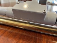
This is my final Mini Corona Stick

The most important upgrade (the difficult one) is my new electrode.
I have managed to blow a hole in the Pyrex tube, centrally located, and the HV cable goes straight into the PCV conduit

This is the shortest path of HV cable (and the safest that I could come up with).

I have another electrode to try - a copper pipe inside a silicon rubber tube with 3mm thick walls.
This was a really tight fit. The cable spade was bolted to a tapped hole in the copper pipe.
This electrode is much cheaper and not as fragile as Pyrex, but needs to be tested.
The rubber tube is about 30mm longer than copper pipe on each side.

The ZVS driver and Flyback housing has been cleaned up.
The ventilated cover is 3D printed in two pieces.
The large white capacitor (Cornell Dublier 2000V DC from my Tesla Coil 🙂 ) was used for tuning.

Once the DC switch and potting compound for the scope HV probe are received, I will send the final post with the stick in operation and general building notes & suggestions that should be sufficient for a knowledgeable person to replicate this gadget.
Regards,
Zvon
This tread is getting old and should be closed with some helpful photos and suggestions.
Down below you will find my last (hopefully the final) prototype.
I have made a number of changes, photos are provided for (in my opinion) important ones.
This is my final Mini Corona Stick
The most important upgrade (the difficult one) is my new electrode.
I have managed to blow a hole in the Pyrex tube, centrally located, and the HV cable goes straight into the PCV conduit
This is the shortest path of HV cable (and the safest that I could come up with).
I have another electrode to try - a copper pipe inside a silicon rubber tube with 3mm thick walls.
This was a really tight fit. The cable spade was bolted to a tapped hole in the copper pipe.
This electrode is much cheaper and not as fragile as Pyrex, but needs to be tested.
The rubber tube is about 30mm longer than copper pipe on each side.
The ZVS driver and Flyback housing has been cleaned up.
The ventilated cover is 3D printed in two pieces.
The large white capacitor (Cornell Dublier 2000V DC from my Tesla Coil 🙂 ) was used for tuning.
Once the DC switch and potting compound for the scope HV probe are received, I will send the final post with the stick in operation and general building notes & suggestions that should be sufficient for a knowledgeable person to replicate this gadget.
Regards,
Zvon
Attachments
Just a quick update,
The silicon rubber insulated electrode works beautifully.
I had to increase the input DC feed to 24V (as expected because of the thicker insulation).
At 24V DC the current draw was about 4A (96W).
This setting produced a nice and uniform corona - an image and a very short clip are below.

The silicon rubber insulated electrode works beautifully.
I had to increase the input DC feed to 24V (as expected because of the thicker insulation).
At 24V DC the current draw was about 4A (96W).
This setting produced a nice and uniform corona - an image and a very short clip are below.
Attachments
Hi,
bought me the ac transformer and testet with a aluminum tube covered by heatshrink tubing.
As grund electrode I used simple alumium foil covered by a 1mm thick lastic board (PVC I guess).
Just drove the ZVS to ~18V and couldn´t see a corona.
Just heard some tickling noise and it quickly smelled after ozone.
Quick treatment in a single stroke of a clear (PE?) bag worked very well.
Got instantely a smooth film of water in the treated area, while there remained streaks of drops in the untreated area.
Think I´m gonna test some more and then start to build a working device. 😉
jauu
Calvin
- Home
- Loudspeakers
- Planars & Exotics
- Membrane Preparation for Coating