Transformer core modeling: https://www.google.com/webhp?source...1&espv=2&ie=UTF-8#q=transformer+core+modeling
EDIT: Also, perhaps of interest: http://www.engr.colostate.edu/ECE562/98lectures/l27.pdf
http://www.engr.colostate.edu/ECE562/98lectures/l28.pdf
EDIT: Also, perhaps of interest: http://www.engr.colostate.edu/ECE562/98lectures/l27.pdf
http://www.engr.colostate.edu/ECE562/98lectures/l28.pdf
Last edited:
Simple Arbitrary IIRs points out that modern processors have dedicated instructions to do big EVIL FIRs efficiently. Most of the better Room EQ programmes use them.
Does anyone know if the MiniDSP and other cheapo boxes do too?
More importantly, can these boxes do efficient arbitrary IIRs with loadsa (or a few) arbitrary feedforward & feedback coeffs?
There is an inescapable EVIL of FIRs. Big FFTs lead to BIG DELAY .. OK for home playback but not for microphones and/or live sound.
I don't know what you mean by dedicated instructions, I consider multiply and add pretty general purpose. The FIR section of my article was more like "Muntzing" the maths.
I have not seen any miniDSP like things that support anything but bi-quads. You would have to program it directly. A modern PC can handle a prodigious amount of maths. How did you handle the frequency warping in the upper octaves? The equations start including transcendentals and do not yield to closed form solution.
Room EQ and playback are fairly latency agnostic unfortunately musicians want 0 latency, and BTW there are zero delay convolution algorithms I've seen them in the AES journal.
EDIT - Good, he has it up for free http://alumni.media.mit.edu/~adamb/docs/ConvolutionPaper.pdf
Last edited:
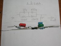
As you are not relying on the 'model' interacting with other impedances to get exact time constants, an approximation would be OKBut I'll give it a shot to come up with a 'correct form' 2 pin model for a cartridge, including the generator. It's said to be 'impossible' because eddy/magnetic losses are heavily non-linear, but even an approximation would be good here.
An 'exact' model would require components that obeyed Lucky's Law .. instead of Ohm V=IR or V=L di/dt or I=C dV/dt
As I said, all these effects need to be compensated so you are better off measuring the damn thing with a Test Record and dreaming up Analogue or Digital EQ for the whole shebang.As Hans posted, what we might be seeing more clearly now with TI loading appears to be other non-ideal characteristics of the cartridge generator, which is pretty interesting per se, I think.
Simple Arbitrary IIRs lets you dream up tiny IIRs. Guru Wurcer's method gives you zillion point FIRs 🙂
I've got some xover optimisation code which can be modified to do electronic feedback EQ .. if I ever get to grips with a compiler that doesn't need a DOS computer (sadly nearly extinct 😡 )
It was a straight DL-103Back at you, was that a straight-up DL-103 (vs S or R or...)?
(but filled with epoxy http://www.diyaudio.com/forums/anal...ifying-dl-103-nov-2009-story.html#post2566488 )
And when you get something wrong you admit it and fix it.
That’s why I am always busy 😀
Thanks for your kind words.
I like your sig line. It brings me back to a friend from UK who could not figure out if reading Pythagoras and Plato allows him to make better moves
or whether he misses the bus more whilst thinking about everything.
Because his moves were entrepreneurial, I suggested he would turn to Sun Zu “The Art of War”
🙂
George
Well, I'd hope that there are many/enough quality MM/MI carts that don't have audioband generator losses, such that a simple law 2L-Rc reasonably applies.As you are not relying on the 'model' interacting with other impedances to get exact time constants, an approximation would be OK
In practice, I've achieved very accurate RIAA playback results without too much difficulty with TI loading, but that does involve selection of carts where mechanical resonance is above the audioband, and 'implicitly' the generator is not lossy, at least on the face of it.
But hey, the journey itself is interesting, and neither generator losses nor mechanical resonance is exactly well charted.............
And a real upside of TI loading, IME, is that it can make for excellent playback from relatively inexpensive MM/MI carts. Which is tangible and worth pursuing, IMO. Besides, it was getting lonely being perhaps the only soul actually using TI MM/MI loading for mainstream playback listening........😉
LD
I'm looking forward to seeing new recordings from George taken with the anti-riaa network, without the ferrite beads and if possible with a better input amp as the LF412.
Hans
I replaced LF 412 with OPA 2134. Also removed the ferrite beads
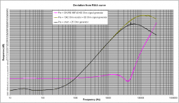
Tests with reverse RIAA network hopefully tomorrow but I think they will show what the second attached diagram shows
George
Attachments
I replaced LF 412 with OPA 2134. Also removed the ferrite beads
Tests with reverse RIAA network hopefully tomorrow but I think they will show what the second attached diagram shows
George
George,
Everybody claiming that the playing a test record is the only real proof of the pudding is of course right.
But to get your fingers behind some of the mysteries, the tests that you are performing are just as informative.
That you have replaced the LF412 by an OPA 2134 is a good step in getting a more precise picture in the FR above 20 Khz.
Bandwidth has been increased by a factor 2 for the two resistor only curves.
That's why I am a bit surprised that the deviation curve with Cart is almost a carbon copy of your previous recording in #503, or is this still the old deviation curve ?
Anyhow, I love the way you proceed and I'm looking forward to see the deviation with anti-riaa in front
And when that is all done, to seeing the results when playing a test record.
Hans
Although circumstances mean I am contributing zero of practical use at the moment I am loving watching the multiple approaches come together (Spherical cow theory, Simulation and practical build).
This is DIY at its best IMHO.
This is DIY at its best IMHO.
or is this still the old deviation curve ?
Hi Hans
Being an expert on making silly mistakes, I had to recheck. I confirm that the curve is based on new data.🙂
The reason that we see almost (*) no change at the cart plot, seems to be the strong influence of the cart characteristics over the preamp characteristics.
(*) There are slight differences though.
0.1dB @ 20KHz, progressing to 1.7dB @ 200KHz
George
LD brings up a good point. What are the better(best) carts that we could expect excellent results with Aurak TI? b&o mmc 1+2 should be great imo, low inductance and they calculate for R1 as=10ohm so do we really need the resistor?
I cannot comment on the MMC1, but assume it would require the Grado style setup, which has the possibility of the lowest noise for those interested in being best on the block 🙂
We do know that that AT series (150, 440 etc) and the Ortoton OM, SuperOM and 2M are all good candidates along with shure V15-IV and V15-V. George is still experimenting with his M97x to see.
As was stated earlier in the thread, laminated cores is the thing to look out for as they reduce eddy currents. We hope to add others to the list over time.
George is still experimenting with his M97x to see.
As was stated earlier in the thread, laminated cores is the thing to look out for as they reduce eddy currents. We hope to add others to the list over time.
Eddy current and hysteresis losses increase exponentially with voltage or flux
Chapters 5, 6
https://core.ac.uk/download/pdf/35462571.pdf
One more verification experiment added to the Q list (how much spherical is the spherical cow ?).
Bill, I don’t know for how long the M97 will survive the tests (it shows remarkable endurance so far) but the day it will die, it’s corps will be donated to science for dissecting.
George
Well I hope it has given you as much enjoyment musically as it has us technically! And hopefully it has some life left in it still.
Eddy current and hysteresis losses increase exponentially with voltage or flux
George, I took a quick look and didn't see where the exponential factor comes in. I tried searching for the word "exponential" with no hits. I also tried searching for the letter e by itself, but I could only find it used to represent voltage.

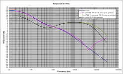
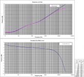
Hans, your anti-RIAA filter as I have built it.
Very accurate within the audio-band: +0.78dB, -0.67dB 20H to 20KHz
Input to output attenuation @1KHz: 70.06dB.
The droop at HF is probably due to parasitic capacitance.
Question: Has anyone measured his anti-RIAA filter at frequencies above 20KHz?
George
Very accurate within the audio-band: +0.78dB, -0.67dB 20H to 20KHz
Input to output attenuation @1KHz: 70.06dB.
The droop at HF is probably due to parasitic capacitance.
Question: Has anyone measured his anti-RIAA filter at frequencies above 20KHz?
George
Attachments
Hi Mark
There are some equations that show this. See the attachment as an example.
George
I am reading the equation with e^2 as meaning the voltage squared. It's just the usual "Power = Voltage^2 / R " formula.
Last edited:
Hans, your anti-RIAA filter as I have built it.
Very accurate within the audio-band: +0.78dB, -0.67dB 20H to 20KHz
Input to output attenuation @1KHz: 70.06dB.
The droop at HF is probably due to parasitic capacitance.
Question: Has anyone measured his anti-RIAA filter at frequencies above 20KHz?
George
There's another pole somewhere what you show can't rise forever the 5 Ohms and the generator resistance limits the rise.
Last edited:
Hans, your anti-RIAA filter as I have built it.
Very accurate within the audio-band: +0.78dB, -0.67dB 20H to 20KHz
Input to output attenuation @1KHz: 70.06dB.
The droop at HF is probably due to parasitic capacitance.
Question: Has anyone measured his anti-RIAA filter at frequencies above 20KHz?
George
Here is the proof.
The Anti Riaa Filter followed by an exact inverse Laplace transformation.
Deviation at 300Khz is -1dB.
Hans

- Home
- Source & Line
- Analogue Source
- mechanical resonance in MMs