Jerk and a few higher order derivatives are sometimes used for motion control system analysis and design. An example would be a train control system, where passengers can brace themselves against a constant acceleration, but not against the sudden jerk when acceleration starts or stops. Therefore, for passenger comfort, s-curve velocity profiles are often used, which serves to keep higher order derivatives smooth and non-singular. More names of the various derivatives here: https://en.wikipedia.org/wiki/Pop_(physics) And a more detailed article here: Beyond velocity and acceleration: jerk, snap and higher derivatives - IOPscience And so on: https://en.wikipedia.org/wiki/Jerk_(physics)
Last edited:
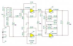
Here's a schematic of what I believe is a balanced iteration of the transimpedance phono preamplifier that luckythedog mentioned a few days ago. Alas, I lost the original schematic. I do know the opamp has been changed from the original AD743 however. And IIRC, there's also a few other changes that maybe bother luckythedog enough to set the record straight for us all.
Attachments
Thanks, that's a good exposition, far better than I can put it!a more detailed article here: Beyond velocity and acceleration: jerk, snap and higher derivatives - IOPscience
Further, material properties we all know and love can alter depending on higher derivatives, esp jolt. For example, some metals can be brittle, some plastics (inc vinyl) can become rigid, and there are some fantastic designer elastomers that become elastic, a soft gunge that bounces !
Point is that in vinyl playback, big stylus jolt can be normal and commonplace, ie big changes of acceleration can happen rapidly. So those pages of the mechanics books that either were ripped out or never got written might apply, and probably do IMO.
I wouldn't bet that anyone has done that, especially back in the day. But I think most of action is south of the cartridge suspension, ie in the cantilever or at the stylus tip, as to the top resonance. I think what one wants from the suspension is an elastomer whose properties don't change with jolt, or that becomes lossy so as to promote damping but at risk of not transcribing what's in the grooves.Pseudoplastic in the cartridge suspension might help. Shear thinning would make compliance higher as acceleration increases. A few engineering challenges to keep it in place tho. Sure someone must have done that at some time...
If there were some material property or constant that related jolt to constant force, which could be zero, I think it could represent time dependant material flow, or time dependant viscosity, and indeed kg s-1 would work mathematically as a unit. But I think most materials would have a small but non-zero value, which becomes relevant at high jolt.
Easy stuff this vinyl playback malarkey 😉 !
LD
Well, that looks a TI variant, but it's not one of mine, is it yours ?Here's a schematic of what I believe is a balanced iteration of the transimpedance phono preamplifier that luckythedog mentioned a few days ago. Alas, I lost the original schematic. I do know the opamp has been changed from the original AD743 however. And IIRC, there's also a few other changes that maybe bother luckythedog enough to set the record straight for us all.
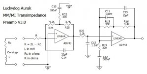
Here's, I think, the first version of Aurak that had a simple way of setting up for different carts. All these were sketches, enough to discuss the concept. Naturally there's potential for improvement, all my stuff is spherical cow based. Op-amps should be 745s or 5534s, not 743s I later realised, for GBW reasons.
LD
Attachments
Last edited:
No it's not one of mine but I played a part in it getting cooked up in the first place.
About four years ago I approached you on another forum about build assistance on the Aurak 3.0 but at the time you weren't interested in discussing the matter so I let you be. The schematic I posted is all I have left from that aborted project (and a few AD743s), the result of having taken the discussion elsewhere. About that time the family relocated and the project was completely aborted when I sold my turntable shortly thereafter.
Thank you for the upload, btw.
Brinkman's and LD's diagrams are basically the same, be it that Brinkman's version is balanced.
With a little tweaking in the second part I could achieve this transfer function.
Square wave response is impeccable.
Hans

With a little tweaking in the second part I could achieve this transfer function.
Square wave response is impeccable.
Hans
Is there any progress understanding mech. resonances in MM Carts so far ?
Scott with his Grado could go al the way up to 40 Khz without a sign of a (second order) mechanical resonance and the STR 112 recordings from John Elison didn't show a clear sign of mech. resonance either with the V15VxMR, although Shure specifies a resonance at 38 Khz.
However the Stanton 681EEE that van Raalte used, was reported to have a very obvious resonance at 21.5 Khz needed to compensate the electrical -3dB at 12 Khz.
Could it be that manufacturers have the choice to optionally include a mech. resonance in their design to compensate for a less perfect electrical response, and that the Grado and V15VxMR do not need such compensations ?
Hans
Source of the 40kHz resonance on Scott's square waves
My apologies if I have missed something - did we establish that the 40kHz signal riding on Scott's square waves was from an electrical system? Or was it an artefact of the measurement system? If it's not clearly either of theose, then is there a mechanical system resonating at 40kHz that we need to consider?
My apologies if I have missed something - did we establish that the 40kHz signal riding on Scott's square waves was from an electrical system? Or was it an artefact of the measurement system? If it's not clearly either of theose, then is there a mechanical system resonating at 40kHz that we need to consider?
Seems there is no choice: mech top resonance seems always there, be it MC, MM or MI, if one provides a level electrical response. What one is then left with, IME, is a resonant series the first term of which typically lies in the 14 - 30kHz region, overlaid with whatever generator roll-off there might be.Could it be that manufacturers have the choice to optionally include a mech. resonance in their design to compensate for a less perfect electrical response, and that the Grado and V15VxMR do not need such compensations ?
I think this is shown in dozens of various cartridge tests on Paul Miller's site Miller Audio 'Avtech', which presents tests of many cartridges under identical conditions. IIRC, included are Grados and many MC carts which can also demonstrate what appears to be a resonant hump in f response, despite having a level electrical response on the face of it. The issue is whether the resonant f is in the audioband rather than whether it's there at all, I conclude. I think PM's stuff is all still up.........
As to the V15, David Laloum's work on characterising the V15 (not sure which variant) was where I first became aware of the resonance. I think it might still be up on his Zevaudio site ?
But I think you're right, Hans, that cartridge manufacturers work with and around it according to the generator and electrical interface; but I also find the resonance is always there IME.
So, for TI loading of MM/MI carts, one needs to choose carts with mech resonances above the audioband and artifacts clear of it, IMO. Which, one would think, is already done for MC carts...... though check out Paul Miller's site.........
LD
Last edited:
Can somebody explain want those two 600 mFd capacitors in the Barney preamp do? I'm baffled. They sort of look like bypass caps in a strange configuration.
Paul Millers website is
Miller Audio Research
You do need to register. July 2006 has a good collection of MC reports. Started with the Roksan Shiraz as this is EMT based. Has a very interesting FR that could be viewed as evidence of TL effects if you were looking for them. 🙂
Edit October 2008 is well worth looking at. Particularly the AT440MLa measurements. Not that it matters to us oldies, but the HF distortion is about 30% of most of the others tested. Much to analyse 🙂
Last edited:
Today's daft question. Taking a brief scan looking for measurements to revisit I noticed some of the distortion plots have a double hump (ortofon 2M Black March 2011). Oddly they also have considerable difference between one channel and another. Maxima at 5 and 15kHz and a minimum at 10kHz. Not what I would expect.
Can somebody explain want those two 600 mFd capacitors in the Barney preamp do? I'm baffled. They sort of look like bypass caps in a strange configuration.
They are just there to keep offset under control.
When using an OPA they can both be replaced by a short circuit.
Hans
Sheesh!! Yet another thread on Arcane Exotica which I was obsessed with in da previous Millenium but will probably never again play with.
Just a few comments
__________________
MCs have more 'output' than most MMs. But its at low volts & low R so you need special techniques to realise this potential 'output'. This was certainly the case with the Ortofons MC/MMs in da 80s & 90s let alone really headbanging stuff like the KoeTsus
__________________
You can easily determine the electromagnetic damping of a cartridge. With my transducer hat on ...
A MC system generates a voltage u = Bl v where
B : Flux in Teslas
l : length of the conductor in metres.
v : velocitiy.
If you put current through the coil, it generates a force F = Bl i
F : Newtons
i : current in Amps.
So knowing the voltage sensitivity of a cartridge at 1cm/s etc, this allows you to calculate the effect of EVIL 5534 input current through the coils bla bla. In ALL cases, this is negligible and I've tried hard to find other effects too without success.
The Bl factor moves parameters between the electrical & mechanical worlds.
If you short out the cartridge, eg with a transimpedance amp, the mechanical side experiences a (viscous) resistance
Rm = (Bl)^2 / Rdc Ns/m or mechanical Ohms
Rdc : DC resistance of the coil
This is exactly the same result as for a loudspeaker & for the same reasons.
So you can check if this will affect mechanical behaviour of the cartridge.
The relation is EXACT for MC cartridges.
A similar but more long winded approach applies for Moving Iron & Moving Magnet ... but assuming the above will always get you within 2% and usually 1% of the 'correct' values.
_____________________
It's not true to say the 'compliance' doesn't affect HF. There's a couple of SHURE papers that show it is a major factor in the 'resonance' at HF.
You can easily check this out for real on the ADC cartridges. Moving the very low mass XLM cantilevers into the somewhat stiffer VLM rubber bungs raised the HF resonance, improves HF trackability bla bla
Caveats about the damping of the bungs ... and I know LD you think the stylus is constrained by the groove bla bla 😀
______________________
A caveat about Test Records. We had several of each type including 1/2 a dozen each of the CBS ones and nearly that for the B&Ks which went up to 50kHz.
Each was stored with full details of each time they were played and by what .. including VTF, arm, anti-skating bias bla bla
If you play a Test Record immediately after one play, you will notice the 'response' has changed ... even with the V15s ... up to IV IIRC.
I think we rested them for 1 day before a subsequent play though that's probably too conservative.
My apologies if I have missed something - did we establish that the 40kHz signal riding on Scott's square waves was from an electrical system? Or was it an artefact of the measurement system? If it's not clearly either of theose, then is there a mechanical system resonating at 40kHz that we need to consider?
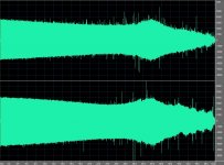
No, in my case I think there are visual artifacts from the software doing a sinc interpolation for display of a squarewave. Here is a 500-50kHz frequency sweep at constant velocity, the bump at 34 seconds is at around 13kHz with the sweep in fractional decades per second. With some imagination one can see the TL effects especially in the lower channel but no sharp resonances. I mentioned yesterday that my recorder aliases so there is actually information here out to 50kHz at 96kHz sampling.
Attachments
Sheesh!!
You can easily determine the electromagnetic damping of a cartridge. With my transducer hat on ...
Sheesh!, is right Richard this stuff is mostly wrong. Try it your self verticle modulation shorting and un-shorting one side of the cart makes not one iota of a difference, no electro-mechanical coupling/damping of any kind. For a MC cart the only motor coupling mechanism that makes any sense is to the 10Hz or so arm/cart resonance. The energy in the arm resonance compared to the motor is absurd (so you don't have to care at all about arm/cart resonance with a virtual ground pre-amp 🙄).
The analogy of MC carts to ribbon mics was always flawed, the reciprocity of a ribbon mic is probably orders of magnitude higher than an MC cart.
Oh yes I also played my test records over and over yesterday and noticed no difference except of course the timing. No two plays of an LP line up nothing to do with vinyl "healing" or whatever the folklore is.
See post #161 the fiddly bits at the end of the waveform line up almost exactly with two plays one right after the other.
Last edited:
Hi Richard, if anything it is typically the other way round, if one considers total power available from the generator into it's own impedance (s/c).MCs have more 'output' than most MMs.
Thing is, this power is tiny compared to mechanical power already moving the cartridge suspension, many orders of magnitude. That is because Bli force is tiny compared to that moving the suspension via the cantilever, many orders of magnitude, yet is applied to the same mechanical impedance.
So although Bli applies, forces arising are trivial, and there is no mechanical damping associated with electrical load of the generator.
DL103, which is well characterised and published, generates c 3nW into its own impedance @5cm/s 1kHz, versus c 0.3mW mechanically available, in principle.
I think if one observes audible or measurable effects through variation of MC loading, they probably arise from non-ideals in the generator, ie electrical/magnetic in origin.
I have never found difference, non-repeatability, nor damage arising, from back to back playback of test records. And I've seen a few ! The biggest issue to avoid for the purpose of testing is eccentricity arising from not necessarily putting a test record back on the spindle in exactly the same position.........
Not much stands scrutiny by way of the lore of vinyl playback, IME. I can't think of any other mainstream, established, multi-billion £ technology product market where seems pretty much everything one thinks one knows about it turns out to be wrong, as Scott puts it !
If only it didn't sound so fine already and still have untapped potential to be better.....
LD
Last edited:
OK - thanks, Scott
Thanks for the explanation - much appreciated. And hence the main focus of discussion is the electrical system.
No, in my case I think there are visual artifacts from the software doing a sinc interpolation for display of a squarewave. Here is a 500-50kHz frequency sweep at constant velocity, the bump at 34 seconds is at around 13kHz with the sweep in fractional decades per second. With some imagination one can see the TL effects especially in the lower channel but no sharp resonances. I mentioned yesterday that my recorder aliases so there is actually information here out to 50kHz at 96kHz sampling.
Thanks for the explanation - much appreciated. And hence the main focus of discussion is the electrical system.
You can easily determine the electromagnetic damping of a cartridge. With my transducer hat on ...
Err.rrh! The aim of my little exercise was to show that even with the most efficient cartridges (which would be certain MCs), any electromagnetic damping is insignificant .. so we are in agreement.Sheesh!, is right Richard this stuff is mostly wrong. Try it your self verticle modulation shorting and un-shorting one side of the cart makes not one iota of a difference, no electro-mechanical coupling/damping of any kind.
Well I don't have a stack of Test Records anymore or even a vinyl playback system so I can only report our Jurassic experience.Oh yes I also played my test records over and over yesterday and noticed no difference except of course the timing. No two plays of an LP line up nothing to do with vinyl "healing" or whatever the folklore is.
See post #161 the fiddly bits at the end of the waveform line up almost exactly with two plays one right after the other.
The HF is the first to start going .. even on one playing.
Can you do a long spectrum analysis of subsequent playings please? You should be able to get better resolution than our steam powered B&K 2307 chart recorder 🙂
I'm reluctant to even ask for this as it horrifies people when they realise their $$$ Test Records are deteriorating even after 1 play.
Last edited:
- Home
- Source & Line
- Analogue Source
- mechanical resonance in MMs