Hi,
Luckythedog, would it not be better to state all forces in Newton and not in its terrean mass equivalent? I use a 17um spherical tip statically pressed down onto the disc with a force of 30mN.
All, not clear to me what mass and what spring? Mass is the diamond and the tip of the cantilever, rite? Spring is inner elasticity of the cantilever and the vinyl, rite? Damping is the vinyl and the inner damping of the cantilever, rite?
Then, does not a hi tracking force dampen resonance, as it raises the influence of the damping of the vinyl? I have a Through The Barricades maxi-single, which sounds nice.
DJs' setups resemble mine, and sure this is not good for LPs, which have too short wavelengths, so trebles get distorted and rolled out. A system which plays all vinyl well must use an elliptical tip and somehow reduce the geometrical problems such as skating.
Uli
Last edited:
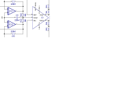
Ok, so I have my twisted pear boards. I'm looking at Hans' schematic Aurak 8, R9 and R10 represent the cartridge R? Also, R1 and R2 are the solved for R from earlier Auraks? The twisted pear schematic shows 2 10k resistors and a 220n Cap that didn't make it over to Aurak 8, do these stay blank, get jumped...? And I only have 7.5k's for R15, R16 will that value be a problem? Thanks 🙂 Very excited about this project.
I can answer in the morning (uk) if Hans isn't up before me. I've got the BOM ready to order for the 4 boards I am makingup, just not hit 'buy' yet.
Cool, thanks Bill. No hurry on this as I still have power supply and other items to build, etc.
I think it's not clear to anyone AFAIK. If the whole topic is subject to scrutiny, common knowledge doesn't make sense, that's for sure........All, not clear to me what mass and what spring? Mass is the diamond and the tip of the cantilever, rite? Spring is inner elasticity of the cantilever and the vinyl, rite? Damping is the vinyl and the inner damping of the cantilever, rite?
Tip mass, conceptually, is the mass equivalent of inertia to movement experienced by a stylus. That seems easy enough, unless one wishes to measure it or specify a number for it.
There are three ways, AFAIK, tip mass has historically been deduced:
1. Measure VTF at limit of hf trackability for a known sine shaped groove, which is limited by how much force is needed to move the stylus (mechanical impedance) and assume inertia is responsible. Seems reasonable, and this is what Japanese manufacturers typically did/still do AFAIK, as per the writings of Yamamoto discussed on this thread.
However, the matter of stylus-groove friction mimics inertia in this method, and so upsets the calculation for tip-mass. Friction varies from record to record, and from stylus to stylus, depending on many variables.
So, IMO, the method typically significantly overstates tip mass and isn't very useful. Tip mass specified this way is just a restatement of trackability performance for a given VTF.
2. Measure hf resonant frequency by observing f response, assume the system is spring-mass, assume a Hertz like vinyl spring constant, then tip-mass can be deduced.
However, vinyl very probably doesn't provide meaningful spring IMO, so the assumed Hertz value for spring constant is misleading/wrong. Rather, IMO the cantilever provides spring, and the hf resonance is due to self-resonance of the cantilever. So the hf resonant f is mostly determined by cantilever dimensions and properties.
So, IMO, tip-mass obtained this way is just a restatement of the hf resonant frequency. Nothing to do with moving inertia of the stylus.........so useless for any purpose involving inertia to motion of the stylus.
3. Calculation by deconstructing cantilever/stylus and weighing/measuring parts, then deducing inertia assuming a rigid model in classic physics.
However, the cantilever isn't rigid, as set out at some length on this thread. So calculation of dynamic inertia is upset, and the method can significantly overstate tip mass.
So 'tip-mass' isn't strictly properly known, IMO.
Neither is the assumption that vinyl provides any meaningful 'spring' safe. For reasons set out on this thread, cantilever flexibility very probably dominates, IMO.
LD
Last edited:
I'm still looking at the SEM images Bill posted from Walton's book, esp the one that allegedly shows significant damage from a single reasonable play.
Having spent a long time looking at it, I still don't get that image........I think there might be some mistake?
There's a continuous gouge along the unmodulated wall that isn't consistent with normal playback at reasonable VTF for healthy cartridge/suspension IMO. So that one knows what one is looking at, the gouge shifts vertically on the flat groove wall following the locus of the groove base, since only the opposite wall is modulated.
Explaining this gouge seems the forensic clue to understanding true conditions for the image. Thoughts ?
It looks more like a single playback at excessive VTF, or with a non-compliant vertical suspension cartridge, or a damaged or poor quality stylus, IMO.
I think this image, and its explanation, might lie at the root of much common knowledge and lore about the nature of vinyl wear, especially as to 'tip-mass'. If it's conditions were 'wrong'.... that might just explain a lot?
LD
Last edited:
I remembered to bring the book back into the office this morning, so as soon as I have a few mins on the real work backlog I will copy this missing page that explains (and confuses) how the image is composited. The upper groove is the path the stylus followed, not a picture of a gouge in the vinyl (at least as described).
R9+R10= RcartOk, so I have my twisted pear boards. I'm looking at Hans' schematic Aurak 8, R9 and R10 represent the cartridge R? Also, R1 and R2 are the solved for R from earlier Auraks? The twisted pear schematic shows 2 10k resistors and a 220n Cap that didn't make it over to Aurak 8, do these stay blank, get jumped...? And I only have 7.5k's for R15, R16 will that value be a problem? Thanks 🙂 Very excited about this project.
(2xLcart-Rcart)/2=R1=R2
7.5K for R15,R16 is not O.K. so put ca. 305K in parallel.
2x10K + 220n ? I can't find what you mean. Please point me to the posting in this thread where you see them.
Hans
Hans, the 2x10k plus 220n is the vcom connection to the output opamp that we discussed on pm a couple of weeks ago and you recommended not be used.
Attachments
Last edited:
That's correct. I would replace the 220N by a short circuit and leave the 2x10K resistors away.Hans, the 2x10k plus 220n is the vcom connection to the output opamp that we discussed on pm a couple of weeks ago and you recommended not be used.
Hans
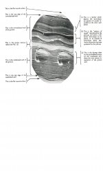
Bother. I got the book out ,put it in the pile to go in my bag and somehow didn't put it in. Phooey. Will copytype the page tomorrow, but for now, if you look at the first scan page (rotated 90 degrees) there is a description of how to read the pictures and you will see how they put together the composite. So you don't actually get to see the unmodulated wall.
The gouge is described as the 'pattern of sound reproduced by the pickup' so it trying to show that the HD due to resonances is huge and in fact that stylus is moving antiphase to the groove. Still no idea how they recorded that. Must be some papers on it somewhere.
The gouge is described as the 'pattern of sound reproduced by the pickup' so it trying to show that the HD due to resonances is huge and in fact that stylus is moving antiphase to the groove. Still no idea how they recorded that. Must be some papers on it somewhere.
Attachments
Hans, in your Aurak 3 schematic you have R2 which controls gain. In the Aurak 8 can R23 be similarly used? Thanks.
No worries and thanks for posting the images so far.Bother. I got the book out ,put it in the pile to go in my bag and somehow didn't put it in. Phooey. Will copytype the page tomorrow, but for now, if you look at the first scan page (rotated 90 degrees) there is a description of how to read the pictures and you will see how they put together the composite. So you don't actually get to see the unmodulated wall.
The gouge is described as the 'pattern of sound reproduced by the pickup' so it trying to show that the HD due to resonances is huge and in fact that stylus is moving antiphase to the groove. Still no idea how they recorded that. Must be some papers on it somewhere.
Well, that published description of what appears to be a deep gouge on the unmodulated wall (labelled '2') seems suitably vague and woolly as to suggest it wasn't clear to the author what had caused it either, IMO............
There are witness lines from the cutter head (labelled '1') which run along the groove on the unmodulated wall, and they serve as a marker for the height of the cutter head in vertical sinusoidal motion: the groove base moves up and down as the modulated wall is cut, and so must the cutter head and so do the witness lines on the unmodulated wall. However, the gouge does not follow the witness lines; rather it has a significant phase offset......😕
It really looks to me as though, for that plot, the stylus had followed a delayed path and cut its own phase shifted gouge in the unmodulated wall, whilst depressing parts of the modulated wall. Besides trying to understand how that is even reasonably possible, surely this can't be normal playback as stated, for any reasonable configuration of VTF/stylus/cartridge............. ?
LD
Last edited:
Can't argue with you on that. Reading the missing page doesn't make it much clearer. Basically as only one wall is modulated the stylus will slide up and down the unmodulated wall, but how on earth Dr Chippindale recorded that is the mystery I have no idea. I'll try and find out more.
As regards reasonable situation, that comes back to the issue of when the plastic deformation limit is reached (and if in fact it can be) which links to forced applied due to resonance.
EDIT: http://www.americanradiohistory.com/Archive-Wireless-World/60s/Wireless-World-1961-07.pdf page 16 onwards has what appears to be Walton's most technical non-JAES paper on record deformation. Probably a good starting point. At some point one of us will have to email UMG and see if the Decca archives can be made available for perusal...
Last edited:
http://www.americanradiohistory.com/Archive-Wireless-World/50s/Wireless-World-1959-04.pdf this one for Richard. I think this is the bendy cantilever he was talking about.
(sorry brain currently only useful for looking things up. All thinking power dissipated)
(sorry brain currently only useful for looking things up. All thinking power dissipated)
I think there were Letters to the Editor asking this exact question.as only one wall is modulated the stylus will slide up and down the unmodulated wall, but how on earth Dr Chippindale recorded that is the mystery I have no idea.
IIRC, the path of the stylus on the unmodulated wall was via the 'polishing' that occurs even with 'etm' 0.6mg It's very faint as can be seen from the other SEM scans.
Sheesh! Deram's 0.6mg was achieved by 1959 😱 Predating V15-II by 7 yrs.http://www.americanradiohistory.com/Archive-Wireless-World/60s/Wireless-World-1961-07.pdf page 16 onwards has what appears to be Walton's most technical non-JAES paper on record deformation. Probably a good starting point. At some point one of us will have to email UMG and see if the Decca archives can be made available for perusal...
The concensus of opinion at that time was if you couldn't afford a V15 or similar, you should buy a Deram as it wouldn't damage your records.
The Deram didn't quite sound as good as V15 etc. The main measured defect was that Separation went to 0dB (around 10kHz) when the cantilever started bending.
Indeed this is still probably a good indicator of how much cantilevers are bending.
This paper & the next one (thanks Bill) has loadsa stuff which will fan the flames of Lucky's Conspiracy Theory .. that all the old cartridge designers were morons & incompetent. 🙂
http://www.americanradiohistory.com/Archive-Wireless-World/60s/Wireless-World-1961-08.pdf follow up with some errata LD will need to see. Sadly the meatiest page appears to be missing. The pictures are same as in the book, suggesting the book was a compendium of the WW articles and the JAES articles.
But Dr. Chippindale remains elusive...
Edit: However Professor Peter Lord at least exists on the internet. Also enjoying reading about Taylor Hobson Talysurfs. I may have to to set Dr Google (George) on the trail here 🙂
But Dr. Chippindale remains elusive...
Edit: However Professor Peter Lord at least exists on the internet. Also enjoying reading about Taylor Hobson Talysurfs. I may have to to set Dr Google (George) on the trail here 🙂
Last edited:
Bill thanks for the links.
There are traces left that Dr. P. Chippindale ( Royal technical College, College of Advanced Technology Salford) participated at the 4th International Congress for Electron microscopy, Berlin 10-17 Sept 1958
I have a relevant book somewhere…
George
But Dr. Chippindale remains elusive...
There are traces left that Dr. P. Chippindale ( Royal technical College, College of Advanced Technology Salford) participated at the 4th International Congress for Electron microscopy, Berlin 10-17 Sept 1958
Also enjoying reading about
I have a relevant book somewhere…
George
Yep, indeed.Hans, in your Aurak 3 schematic you have R2 which controls gain. In the Aurak 8 can R23 be similarly used? Thanks.
Hans
- Home
- Source & Line
- Analogue Source
- mechanical resonance in MMs