Repeat until the full power driver/enclosure measures and sounds correct.
Hello All,
Back again to visit and add a few things.
This time I have been checking out other thoughts about driver impedance measurement. It seems that things are less well connected to a simple set of driver parameters that can be plugged into speaker simulation software. It is more complex than that. There is a range of things between small signals and full on watts to drive a sub-woofer. It appears to include a fair amount of wishing and hoping if you intend to measure speaker parameters with small signal input and expect to forecast speaker driver performance in a fabricated enclosure.
One example input voltage makes a significant difference to resonant frequency. Temperature and humidity also contribute to the measured/calculated results.
Then there are different models that differ from the standard Theile Small model. The Wright and LR-2 models produce results that are more accurate than the old school TS/P. Still not indicators of full power performance. I get the impression that the speaker manufactures select test voltages and conditions and then tweak the published “TS/P’s” to ensure that their drivers will perform in enclosures calculated by the standard speaker enclosure simulation software.
Depending on how serious you are; measuring TS/P is just a first step in matching a driver to a enclosure. I see it going like this; measure the driver, fabricate a enclosure, measure the driver/enclosure and repeat until the full power driver/enclosure measures and sounds correct.
Thanks DT
Food for thought.
https://www.klippel.de/fileadmin/kl...iterature/Papers/Voice_Coil_ Impedance_04.pdf
It is more complex than that
As i believe i said earlier, T/S parameters are scalars collapsed from the curves that represent the changing parameters under dynamic conditions (and with changes of volume control).
The changes often tend to balance one another, but i like to design a box for greater tolerance to these dynamic changes. I have almost always found the factory m=numbers a good start so the place where something like LMS collapes to scalars is most often — in my experience — a good compromise for real life use.
Subwoofers probably have the largest shifts, so some finese in their design really helps.
dave
Back to testing drivers, Mid-Bass drivers this time.
I am looking to make a pair of Mini-2-Ways this time.
There are a couple of mid-bass candidate drivers sitting here on the bench. This is for fun so we are open to other thoughts.
I have read a couple of places that amplifiers and crossovers perform better wit Zobels or compensation networks in parallel with the mid-bass driver. Perhaps even less distortion.
A couple of references below.
https://leachlegacy.ece.gatech.edu/papers/zobel/zobel.pdf
https://www.klippel.de/fileadmin/kl...iterature/Papers/Voice_Coil__Impedance_04.pdf
https://audioxpress.com/article/voice-coil-lab-notes-improved-zobel-network

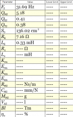
I have a couple of test plots of Impedance Magnitude and impedance phase for each below.
I have resistors on order for the Zobels.
I am looking to make a pair of Mini-2-Ways this time.
There are a couple of mid-bass candidate drivers sitting here on the bench. This is for fun so we are open to other thoughts.
I have read a couple of places that amplifiers and crossovers perform better wit Zobels or compensation networks in parallel with the mid-bass driver. Perhaps even less distortion.
A couple of references below.
https://leachlegacy.ece.gatech.edu/papers/zobel/zobel.pdf
https://www.klippel.de/fileadmin/kl...iterature/Papers/Voice_Coil__Impedance_04.pdf
https://audioxpress.com/article/voice-coil-lab-notes-improved-zobel-network
I have a couple of test plots of Impedance Magnitude and impedance phase for each below.
I have resistors on order for the Zobels.
Attachments
-
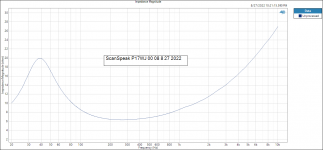 Impedance Magnitude ScanSpeak p17WJ 00 08 8 27 2022.PNG15.5 KB · Views: 72
 -
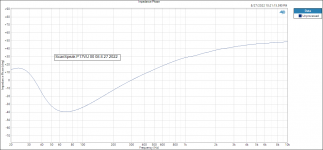 Impedance Phase ScanSpeak p17WJ 00 08 8 27 2022.PNG14 KB · Views: 73
 -
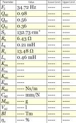 Thiele-Small ScanSpeak P17WJ 00 08 9 1 2022.png9.5 KB · Views: 77
 -
 Impedance Magnitude Purifi PTT6.5X NFA 01B 08 8 27 2022.PNG16.8 KB · Views: 68
 -
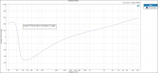 Impedance Phase Purifi PTT6.5X NFA 01B 08 8 27 2022.PNG13.9 KB · Views: 70
 -
 Thiele-Small Purifi PTT6.5X NFA 01B 08 8 27 2022.PNG9.1 KB · Views: 68
Last edited: