Hi Pafi
I don't think you have thought enough about issue at hand. The initial results look great - but simply aren't credible.
Thank you for neglecting my thoughts! ;-)
Thinking about a giantic set of data without a clear system is good only for confusing. The selection of comparable data and ignoring unsure and/or incomparable data is a neccessary step of debugging. I ignore distracting info deliberately. Logic works for simple statements only, and I prefer logic.
I ask again: Why not credible? Why do you think Walton's result are the correct ones? If the "degradation" is always there (except for very bad ones, whose error hides the measurement error), not depending on the design, then most probably it is not the problem of the regulator, but the measurement, since that is the common part.
sorry, not visible on my phone.I've attached a graphic of Jack's results hereto.
I don't know what you mean "the attenuation" and what is the relevance to the other issues. Most probably this is an other problem. I can't see real similarity with the earlier results shown here. And I can't see a relevant reference to compare this result to.
The issue is not the coupling in of external periodic signals.
I can't agree, and can't see your reason to think this.
The issue is attenuation of the measured output.
This can happen extremely difficult. I see no possibility for this. But the other way, addition of an inductively coupled signal is a known and very frequent issue. You need an extremely low inductive coupling to produce -110 dB of signal. For example 10nH in the interconnection and 10nH at LNA input with a coupling factor of K=0.001 and a DUT input impedance of 3 ohms at 90 kHz gives something around this level. Building a setup much under these level of coupling is not quite regular.
I suspect an inductor (low pass) filter created by the ground setup but the inductance has to be quite large, however, to create with the 24R load a low pass filter down 20dB at 100kHz. Still thinking about it.
As you see you need to assume improbably high parasitic inductive element to make your explanation work. What is more: the direction of the changes you made is in opposite to the experienced result. You increased inductance and got higher output voltage.
You can check your theory easily: measure input voltage of regulator directly! If you can find much higher voltage at high freq with the big loop setup then with the twisted interconnect, then you are right. But I see no chance for this.
Be happy! You did it better than others!
But you also have a very simple way to evaluate/validate your measurement setup: measure a perfect filter! Input impedance should be similar to the normal DUT (parallel RC), and GND connection should exist (a piece of wire), but define its output to be exactly at the output GND. Its "PSRR" is infinite. Every output signal you measure with this is a false signal created by the setup. Every result while measuring DUT significantly above that dummy test level is correct.
... 20dB/decade roll-off...
[...]
30k -117.6
40k -114.6
50k -112.1
60k -110.2
70k -107.6
80k -106.9
90k -104.5
This is more than 20 dB/decade. This fits to the effect chain I described in my last post (additive 2nd order derivative with some lossy elements).
But Walton's error can be different...
Pafi
One check of the test setup is to compare the results of a known regulator when tested with this setup with PSRR data conducted by others of the same regulator. My test of the LM317 resulted in flat PSRR from 30kHz to 90kHz. This doesn't match or even come close to published data for this well-known regulator. The TI paper contains a PSRR evaluation of the LM317 in Figure 7. Note the roll-off in PSRR of around 20dB from 10kHz to 100kHz, no doubt a result of the dominant pole and roll-off of loop gain in its circuit.
The LTspice simulation of my discrete regulator also forecasts a circa 20dB fall in PSRR from 10kHz to 100kHz. Again you can see that this matches the roll-off in loop gain in the modelled circuit and we know such a roll-off is necessary for the feedback circuit to be stable.
My latest test of the discrete regulator (post 74 above) showed a 9kHz - 90kHz change in PSRR of 121.4-104.5 = 17dB. I can't test 100kHz and 9kHz is a little short of the expected inflection point shown in the sim I referenced before so I'd expect it to be a bit shy of 20dB. I'm not sure 17dB is "accurate" but certainly 17dB is likely a more correct result than the former 12dB. It's at least heading more in the expected direction than otherwise.
So then the question becomes what in this test setup could be masking the expected roll-off in PSRR (in both the discrete voltage regulator and the known LM317 - and for that matter the LM7812 which was also tested)? For better or for worse, I'm referring to this as attenuation of the output signal - an attenuation/reduction of the residual ripple one would expect to see. How that is occurring remains to be figured out and is the question of the day.
The input stimulus has been monitored and shown to remain at the requisite 1Vpp ripple for all frequencies of interest during testing. (Surely if an offset was being coupled into the input one would see a rolloff in the stimulus ripple.) The sound card FR has been shown flat (enough for these purposes) and the preamp+sound card combo flat also. A further check of the test setup was done by replacing the regulator DUT with a simple voltage divider directly at the output of the rail driver (together with a 470n cap and 0.5A load - those used at the input and output of the discrete regulator DUT during testing) and it was shown flat - no decline in residual ripple. All as expected. And yet when I place a regulator circuit between rail driver and preamp - connected by wires - I get unexpected results. Lowering the impedance of the GND connection between rail driver and regulator moved the needle decidedly towards results that were closer to those expected. The challenge is to understand why and potentially improve the test setup if need be (if it can be done within reason).
For example, a first order low pass filter with a corner frequency of around 10kHz would mask the expected roll-off in PSRR/rise in residual ripple. RC or RL? Reducing the impedance of the ground connection between reg DUT and rail driver 'improved' results. Perhaps this points to RC as reduced R would shift the cutoff frequency further out...
If my wire connections truly do yield a real, positive improvement in PSRR then great! But can it be that 10cm of twisted-pair wiring from ripple generator to ripple eater can be a ripple eater itself? I'm sceptical.
Attachments
Last edited:
SGK,
Before anything else: you must know that I don't want to offend you! I try to explain as much results as possible, and guide you to understanding, but this requires to deny faulty premises and deductions (and insufficient replies) you fall back to. If you release the faulty/ambiguous/irrelevant results and start a clean measurement method, and listen to the explanations, then you can finally understand everything.
This is true, but not for only to this domain. There is strong deviation at every freq.
I must make myself clear: when I wrote the first measurement was correct, then I focused only on your question: what is the effect of the different ground connections. The first one was better. But everything else can be faulty, I see no evidence about the rest. Or can be correct either. Who knows? I see no calibration test result.
Correct evaluation can be done only by really known etalons. You say LM317 IC is known. OK. But a regulator is not just an IC, there are other components and a PCB. The other components also affect the result strongly. Unless you checked if everything is done the same way as others done you cant say you evaluated the setup this way. And even if the results are equal (quantitatively, not just showing some similarity like a 20 dB/decade slope) then you can say that at this region the setup works well, the transmittion seems to be more-or less linear.
I can see giantic deviation between your and TI's result that is not limited to high frequency. But no circuit details are published here, so the results are not comparable in any way. There must be some big difference, but I can't investigate what it is. I suggest you to ignore those results, since nothing is correct about it.
Important sidenote: you wrote OnSemi and TI published very different PSRR results. Doesn't this ring an alarm bell about using it as reference?
But even if you done a correct and successful validation with LM317, this shows only linearity and gain, but nothing about the lower limit of the measurement. At a much lower signal level additive errors become dominant. This is the kind of error you must check with the dummy, "perfect filter". You know: like shorting a resistance meter to see if correctly show 0. This test is neccessary (but not satisfactory alone) to validate the freq and signal level area where you found the dependence of ground connection.
After making the setup free from ground loops and other unwanted coupling you can start calibration. Calibration test can be made by modifying the dummy filter a little: attach 1 ohm + 100 uF series RC (tied as short as possible!) between output GND and output, and 100 k from input to output. This must produce a -100 dB transfer from 1.6 kHz to 90 kHz, and -20 dB/d slope under the corner freq (1.6 kHz). (If the result is different, then you can start to debug according to the deviance.)
No doubt? Dominant pole at 10 kHz? And do you assume the forward path transmittion function from input rail to output was constant? You are very confident about very complex questions... What do you think about the giantic difference in the results at almost any frequency?
I asked if you have simulation results comparable to the measurements, but no answer. This would be a solid stand-point. Post these together with description and the relevant contradictional measurements, and we can start to analyze. But "20dB fall" alone is not a real characteristic feature. It can come from many different things in a real circuit. Every value must mach in a good measurement.
You measure PSRR. Compare actual PSRR values, not a randomly grabbed gradient in a narrow domain! And don't "refer" to the simulation, show it! You can do it once easily, other ones must search for one by one, and after all you asked for help.
Your question contains a hidden statement: the same effect causes both deviance. But I see no reason to this assumption. I know it was a simpler explanation than assuming multiple problems, but I see no possible effect chain with "the attenuation" theory that is not contradictional to the relevant and comparably results. "Every theory must be as simple as possible, but no more simple!" - A. Einstein (not exactly quoted).
Attenuation is normally defined as the level reduction in the same circuit, between 2 different signals. You applied to the same signal but with modified circuit. I find it quite disturbing, and can distract from the real understanding. You try to find a real attenuation network with the parameters you see, but that attenuator never existed.
So you proved no attenuation here. And the rest of the circuit is unchanged while changing interconnect. So there is no place left for attenuation anywhere. You provided a strong disproof for the attenuation theory.
"Offset" - do you mean an additive AC signal component?
"Input" - do you mean input of LNA (wich is output of DUT)?
"Stimulus ripple" - do you mean input signal of DUT?
This deduction ignores the effect I explained during whole time: there is a variable bypass path parallel to the DUT.
All? You said "flat" many times, but despite of the direct question from Mark you didn't state actual numbers. How many dB? And why scaled in dB/sqrtHz? Soo many problematic/ not described details...
Lowering the impedance of the GND connection? Do you think there is such quantity as impedance of a wire without defining a closed loop? Such thing is not existing. You always must define the forward and reverse current path to define impedance. Inductance (reactive part of impedance) is the flux inside the loop devided by current. In a big current loop inductance is higher than in a tightly twisted pair. But this is not the only problem with your explanation. The result is not a reduction of a problem but a random coincidence. Don't confuse yourself!
This is what i did.
And where could have been it? Your measurements discarded every place for it.
What do you mean improved? Better PSRR or closer to your expectation? These are opposite. And as we see there is an ambiguousness in "reducing impedance" also. This is too much for me to follow. For you also, because you have false/questionable premises in both sides.
Im sceptical too. I definitely don't think and didn't imply it eats ripple. It only lacks radiating it unlike a big loop. This is what I try to explain. I don't see a sign you understood it, but I keep trying as long as you show interest.
Before anything else: you must know that I don't want to offend you! I try to explain as much results as possible, and guide you to understanding, but this requires to deny faulty premises and deductions (and insufficient replies) you fall back to. If you release the faulty/ambiguous/irrelevant results and start a clean measurement method, and listen to the explanations, then you can finally understand everything.
Pafi
One check of the test setup is to compare the results of a known regulator when tested with this setup with PSRR data conducted by others of the same regulator. My test of the LM317 resulted in flat PSRR from 30kHz to 90kHz. This doesn't match or even come close to published data for this well-known regulator.
This is true, but not for only to this domain. There is strong deviation at every freq.
I must make myself clear: when I wrote the first measurement was correct, then I focused only on your question: what is the effect of the different ground connections. The first one was better. But everything else can be faulty, I see no evidence about the rest. Or can be correct either. Who knows? I see no calibration test result.
Correct evaluation can be done only by really known etalons. You say LM317 IC is known. OK. But a regulator is not just an IC, there are other components and a PCB. The other components also affect the result strongly. Unless you checked if everything is done the same way as others done you cant say you evaluated the setup this way. And even if the results are equal (quantitatively, not just showing some similarity like a 20 dB/decade slope) then you can say that at this region the setup works well, the transmittion seems to be more-or less linear.
I can see giantic deviation between your and TI's result that is not limited to high frequency. But no circuit details are published here, so the results are not comparable in any way. There must be some big difference, but I can't investigate what it is. I suggest you to ignore those results, since nothing is correct about it.
Important sidenote: you wrote OnSemi and TI published very different PSRR results. Doesn't this ring an alarm bell about using it as reference?
But even if you done a correct and successful validation with LM317, this shows only linearity and gain, but nothing about the lower limit of the measurement. At a much lower signal level additive errors become dominant. This is the kind of error you must check with the dummy, "perfect filter". You know: like shorting a resistance meter to see if correctly show 0. This test is neccessary (but not satisfactory alone) to validate the freq and signal level area where you found the dependence of ground connection.
After making the setup free from ground loops and other unwanted coupling you can start calibration. Calibration test can be made by modifying the dummy filter a little: attach 1 ohm + 100 uF series RC (tied as short as possible!) between output GND and output, and 100 k from input to output. This must produce a -100 dB transfer from 1.6 kHz to 90 kHz, and -20 dB/d slope under the corner freq (1.6 kHz). (If the result is different, then you can start to debug according to the deviance.)
The TI paper contains a PSRR evaluation of the LM317 in Figure 7. Note the roll-off in PSRR of around 20dB from 10kHz to 100kHz, no doubt a result of the dominant pole and roll-off of loop gain in its circuit.
No doubt? Dominant pole at 10 kHz? And do you assume the forward path transmittion function from input rail to output was constant? You are very confident about very complex questions... What do you think about the giantic difference in the results at almost any frequency?
The LTspice simulation of my discrete regulator also forecasts a circa 20dB fall in PSRR from 10kHz to 100kHz. Again you can see that this matches the roll-off in loop gain in the modelled circuit and we know such a roll-off is necessary for the feedback circuit to be stable.
I asked if you have simulation results comparable to the measurements, but no answer. This would be a solid stand-point. Post these together with description and the relevant contradictional measurements, and we can start to analyze. But "20dB fall" alone is not a real characteristic feature. It can come from many different things in a real circuit. Every value must mach in a good measurement.
My latest test of the discrete regulator (post 74 above) showed a 9kHz - 90kHz change in PSRR of 121.4-104.5 = 17dB. I can't test 100kHz and 9kHz is a little short of the expected inflection point shown in the sim I referenced before so I'd expect it to be a bit shy of 20dB. I'm not sure 17dB is "accurate" but certainly 17dB is likely a more correct result than the former 12dB. It's at least heading more in the expected direction than otherwise.
You measure PSRR. Compare actual PSRR values, not a randomly grabbed gradient in a narrow domain! And don't "refer" to the simulation, show it! You can do it once easily, other ones must search for one by one, and after all you asked for help.
So then the question becomes what in this test setup could be masking the expected roll-off in PSRR (in both the discrete voltage regulator and the known LM317 - and for that matter the LM7812 which was also tested)?
Your question contains a hidden statement: the same effect causes both deviance. But I see no reason to this assumption. I know it was a simpler explanation than assuming multiple problems, but I see no possible effect chain with "the attenuation" theory that is not contradictional to the relevant and comparably results. "Every theory must be as simple as possible, but no more simple!" - A. Einstein (not exactly quoted).
For better or for worse, I'm referring to this as attenuation of the output signal - an attenuation/reduction of the residual ripple one would expect to see. How that is occurring remains to be figured out and is the question of the day.
Attenuation is normally defined as the level reduction in the same circuit, between 2 different signals. You applied to the same signal but with modified circuit. I find it quite disturbing, and can distract from the real understanding. You try to find a real attenuation network with the parameters you see, but that attenuator never existed.
The input stimulus has been monitored and shown to remain at the requisite 1Vpp ripple for all frequencies of interest during testing.
So you proved no attenuation here. And the rest of the circuit is unchanged while changing interconnect. So there is no place left for attenuation anywhere. You provided a strong disproof for the attenuation theory.
(Surely if an offset was being coupled into the input one would see a rolloff in the stimulus ripple.)
"Offset" - do you mean an additive AC signal component?
"Input" - do you mean input of LNA (wich is output of DUT)?
"Stimulus ripple" - do you mean input signal of DUT?
This deduction ignores the effect I explained during whole time: there is a variable bypass path parallel to the DUT.
The sound card FR has been shown flat (enough for these purposes) and the preamp+sound card combo flat also. A further check of the test setup was done by replacing the regulator DUT with a simple voltage divider directly at the output of the rail driver (together with a 470n cap and 0.5A load - those used at the input and output of the discrete regulator DUT during testing) and it was shown flat - no decline in residual ripple. All as expected.
All? You said "flat" many times, but despite of the direct question from Mark you didn't state actual numbers. How many dB? And why scaled in dB/sqrtHz? Soo many problematic/ not described details...
And yet when I place a regulator circuit between rail driver and preamp - connected by wires - I get unexpected results. Lowering the impedance of the GND connection between rail driver and regulator moved the needle decidedly towards results that were closer to those expected.
Lowering the impedance of the GND connection? Do you think there is such quantity as impedance of a wire without defining a closed loop? Such thing is not existing. You always must define the forward and reverse current path to define impedance. Inductance (reactive part of impedance) is the flux inside the loop devided by current. In a big current loop inductance is higher than in a tightly twisted pair. But this is not the only problem with your explanation. The result is not a reduction of a problem but a random coincidence. Don't confuse yourself!
The challenge is to understand why and potentially improve the test setup if need be (if it can be done within reason).
This is what i did.
For example, a first order low pass filter with a corner frequency of around 10kHz would mask the expected roll-off in PSRR/rise in residual ripple. RC or RL?
And where could have been it? Your measurements discarded every place for it.
Reducing the impedance of the ground connection between reg DUT and rail driver 'improved' results.
What do you mean improved? Better PSRR or closer to your expectation? These are opposite. And as we see there is an ambiguousness in "reducing impedance" also. This is too much for me to follow. For you also, because you have false/questionable premises in both sides.
Perhaps this points to RC as reduced R would shift the cutoff frequency further out...
If my wire connections truly do yield a real, positive improvement in PSRR then great! But can it be that 10cm of twisted-pair wiring from ripple generator to ripple eater can be a ripple eater itself? I'm sceptical.
Im sceptical too. I definitely don't think and didn't imply it eats ripple. It only lacks radiating it unlike a big loop. This is what I try to explain. I don't see a sign you understood it, but I keep trying as long as you show interest.
SGK,
Before anything else: you must know that I don't want to offend you!
I understand. And likewise in return. Thanks for your interest and input.
Important sidenote: you wrote OnSemi and TI published very different PSRR results. Doesn't this ring an alarm bell about using it as reference?
Both charts exhibit the same rolloff in PSRR above 10kHz which is the issue under discussion. In the case of the OnSemi data sheet, the slope is a little greater than 20dB/decade. I don't doubt that there are multiple variables at work which can affect the overall performance (e.g. my LM317 circuit used 22uF from Adj pin to GDN to improve performance) but a fundamental character of such regulator circuits is a roll-off in PSRR at higher frequencies. This was not present in my first tests with the twisted pair wiring between rail driver and reg DUT. This, and only this, is the topic of this debate for now.
After making the setup free from ground loops and other unwanted coupling you can start calibration. Calibration test can be made by modifying the dummy filter a little: attach 1 ohm + 100 uF series RC (tied as short as possible!) between output GND and output, and 100 k from input to output. This must produce a -100 dB transfer from 1.6 kHz to 90 kHz, and -20 dB/d slope under the corner freq (1.6 kHz). (If the result is different, then you can start to debug according to the deviance.)
Not this exact test but have you looked at posts 41-49 in this thread? This was a test of the sound card to ensure there was no issue on that side of things. In posts 52 and 57 I presented results with the rail driver, preamp + sound card with a straight divider. I did not do the latter with the cap rolling off attenuation but it is clear that nothing is being coupled in or otherwise to offset an expected circa 20dB roll-off in PSRR in the higher frequencies when the reg DUT is replaced by a simple resistor divider.
I asked if you have simulation results comparable to the measurements, but no answer. This would be a solid stand-point. Post these together with description and the relevant contradictional measurements, and we can start to analyze. But "20dB fall" alone is not a real characteristic feature. It can come from many different things in a real circuit. Every value must mach in a good measurement.
You measure PSRR. Compare actual PSRR values, not a randomly grabbed gradient in a narrow domain! And don't "refer" to the simulation, show it! You can do it once easily, other ones must search for one by one, and after all you asked for help.
I have on several occasions suggested you take a look at the sim results in post 4. Do you want the LTspice files? Note the rolloff in simulated PSRR consistent with the roll-off in loop gain in the circuit's feedback loop. The glaring issue in the results of my initial measurements has always been the lack of roll-off. There might be other things to discuss but for now that's what I am trying to understand - that and why the measured rolloff is so absolutely sensitive to the ground connection between rail driver and reg DUT.
I'm open to any theory which explains this.
Attenuation is normally defined as the level reduction in the same circuit, between 2 different signals. You applied to the same signal but with modified circuit. I find it quite disturbing, and can distract from the real understanding. You try to find a real attenuation network with the parameters you see, but that attenuator never existed.
By "attenuation" I mean something that is offsetting the predicted rise in residual ripple with increasing frequency above about 10kHz. We see that this 'something' is very sensitive to the GND connection between rail driver and reg DUT. I think that's as far as we have gotten. Call it what you want, that is merely how I have chosen to label it.
"Offset" - do you mean an additive AC signal component?
"Input" - do you mean input of LNA (wich is output of DUT)?
"Stimulus ripple" - do you mean input signal of DUT?
To test PSRR we 'input' a ripple of known quantity at freq x to the regulator under test. I refer to the input of the reg DUT. I refer to the stimulus ripple as being the ripple generated by the rail driver at the chosen frequency of interest and at the Vpp of interest (the latter remaining constant at 1Vpp in these tests). If I have referred to 'offset' I mean anything which is offsetting the expect rise in residual output ripple from the reg DUT as frequency increases.
All? You said "flat" many times, but despite of the direct question from Mark you didn't state actual numbers. How many dB? And why scaled in dB/sqrtHz? Soo many problematic/ not described details...
I think it would be tiresome for all if I repeated scores of test observations only to conclude that the observation for each frequency tested was within a dB of that expected by simple computation. If you would prefer the scaling in some other form I can provide, but I don't think that's going to help much. If I replace the regulator under test (only) in the test setup with a voltage divider at the output of the rail driver/ripple generator (leaving the same capacitance to be driven and Iload) and the residual ripple (what's left of the 1Vpp ripple stimulus after the voltage divider) measures the same at all frequencies I don't care what quantity it is expressed in - the point that's relevant there is that in that situation (a simple simplification of the test setup) there is nothing in the test setup causing a roll-off in measured results.
What do you mean improved? Better PSRR or closer to your expectation? These are opposite. And as we see there is an ambiguousness in "reducing impedance" also. This is too much for me to follow. For you also, because you have false/questionable premises in both sides.
When results come closer to expectations one can consider it an improvement. But this is semantics only.
So, from the simulation of the discrete regulator I built, from observing the PSRR charts of known regulators made by competent engineers with very sophisticated test setups and experience (and even from simulating such IC regulators) we can see that one would expect a roll-off in PSRR for both the discrete regulator and the LM317 of around 20dB per decade (or even more in the latter case) beyond circa 10kHz. Certainly flat PSRR would not be an expected result. Until we agree on this the conversation can go no further as this is the topic under discussion.
If we do agree on this then I think we ought to agree that it is odd/puzzling/intriguing (choose whatever adjective you prefer) that my first tests of the discrete regulator and LM317 did not appear to show this expected outcome. As noted above, there might be other things of interest, but for now this is the standout peculiarity of the results thus far - that and the fact that the slope (were the results plotted) of the residual ripple voltage by frequency beyond 10kHz is so sensitive to the nature of the ground connection between ripple driver and reg DUT. Is the latter coincidence? Maybe. Odd? Yes. Explanation? Not yet uncovered. For as long as it is an unexpected result, I query the test setup to see if it is masking the expected outcome in some way.
Im sceptical too. I definitely don't think and didn't imply it eats ripple. It only lacks radiating it unlike a big loop. This is what I try to explain. I don't see a sign you understood it, but I keep trying as long as you show interest.
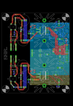
I was surprised that the GND connection between rail driver/ripple generator and reg DUT would be a factor. (Obviously else I would have set the first tests up differently.) As I noted, I assume it is not uncommon to have a high performance regulator circuit supplied DC+some ripple component via twisted wiring such as I used. It is intriguing that thicker ground connection with strong Faston connectors directly between the main ground planes rather than thin wire soldered to or crocodile clips to pins inserted into drill holes made for filter caps (look at the board layout images to see just how more directly the ground planes are connected) seems to make such a difference. Maybe its more about improving the GND connection from preamp to ripple generator - dunno. I'm stumped. I just tossed out an idea for debate. That idea was simply that something in the overall test setup ground connections was either creating a first order low pass filter of Vout or perhaps more likely the opposite with respect to GND such that the potential between the two as measured by the preamp/sound card (a combo which has been shown to have flat FR on its own) is less than expected as the stimulus frequency rises.
Alternate theory?
I understand. And likewise in return. Thanks for your interest and input.
...Both charts exhibit the same rolloff in PSRR above 10kHz which is the issue under discussion.
My point is that "rolloff" is a very misleading characteristic, incapable to distinguish between an additive and a multiplicative error. Wrong way, come back!
Not this exact test but have you looked at posts 41-49 in this thread? This was a test of the sound card to ensure there was no issue on that side of things.
That is good, but at a completely different level. Probably your setup is linear, but maybe not. A correct test must be close the intended usage, or you must assure other way that the results are relevant. The other problem is that you didn't check dependency from DC input. Theoretically it is independent. But theoretically the whole setup is good, while you say there is something wrong, so just stay with actual measurement!
In posts 52 and 57 I presented results with the rail driver, preamp + sound card with a straight divider. I did not do the latter with the cap rolling off attenuation but it is clear that nothing is being coupled in or otherwise to offset an expected circa 20dB roll-off in PSRR in the higher frequencies when the reg DUT is replaced by a simple resistor divider.
Of course, since the signal level was much-much higher! You can add an ant to an ant, and get 6 dB gain, but if you add an ant to an elephant, then you see no change. This shows that the error is NOT an attenuation, but an addition. This is the reason you can't find it at high level. You are searching for the wrong type of error that was never been there.
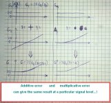
Look at the attached pictures! Do you see now how an additive error can give a result you want to achieve? And that this is the only type of error can explain your results?
I have on several occasions suggested you take a look at the sim results in post 4.
Where? And post 4 of what topic? There is no simulation in post 4 of this topic.
Attachments
Where? And post 4 of what topic? There is no simulation in post 4 of this topic.
My error. Sorry. Post 10.
The rest is again semantics. We can choose different adjectives to describe the same characteristics in similar ways. An addition of a negative attenuates. The point is that the result is lower than expected. A residual ripple increasing with frequency can be described as reducing PSRR (or a roll off in PSRR).
What test do you think would be informative in figuring out where the test setup is failing or, alternatively, my implementation of an LM317 circuit bests all before it?
Last edited:
When results come closer to expectations one can consider it an improvement.
My doctor said Im fat, I must lose weight. So I cut my leg. I improved myself, do you agree? The logic behind it is exactly the same as in your case.
But this is semantics only.
Semantics is science of meaning. If meaning is so unimportant that the 'logic' above can be accepted, then no communication and no logical thinking is possible. And I can say this to "attenuation=any deviance" and some other abusal of terminology. With good reason.
. I'm stumped. I just tossed out an idea for debate. That idea was simply that something in the overall test setup ground connections was either creating a first order low pass filter of Vout or perhaps more likely the opposite with respect to GND such that the potential between the two as measured by the preamp/sound card (a combo which has been shown to have flat FR on its own) is less than expected as the stimulus frequency rises.
Alternate theory?
I presented. Im waiting for you to join talking about.
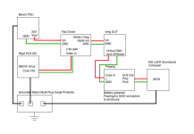
Your scheme of the test setup is nearly finished, only some inductors are missing in GND and interconnection (and the impedance between safety earth and signal GND).
Last edited:
My error. Sorry. Post 10.
The rest is again semantics. We can choose different adjectives to describe the same characteristics in similar ways.
Absolutely no! I don't talk about adjectives, I talk about math and networks! You can't say addition and multiplication are the same! Also you can't say G2 and A are the same, and obviously the results at high level (G' and G'') are not the same. The 2 ways I produced the low level results are completely different, only the result are the same. But the difference of the methods become obvious at high level as I shown. The two network we are talking about are completely different. And only one of them can reproduce the results you experienced the one with additive error. This is not similarity, this is math logic.
.An addition of a negative attenuates
You seems to ignore the mathematical rules of logarithmic scales or rule of signal propagation. Addition happens on linear scale. Addition in linear scale is NOT attenuation.
The point is that the result is lower than expected. A residual ripple increasing with frequency can be described as reducing PSRR (or a roll off in PSRR).
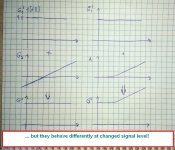
Yes, this is shown on the right side of my drawing. But as you already seen this predict the same reduction at higher level, that is NOT seen. So this modell must be false. Only the left side shows results that maches with the reality.
What test do you think would be informative in figuring out where the test setup is failing or, alternatively, my implementation of an LM317 circuit bests all before it?
If you can't understand my drawings and my simple examples, then I can't suggest any tests. Basics of math first.
Signal to measure: 1 uV
Error1= addition of 9 uV
Error2= gain of 20 dB
In case of Error1 1uV+9uV equals to 20 dBuV
In case of Error2 1uV×10 is also 20 dBuV
But when you measure 1 mV of signal, then
Error1 gives 1009uV => 60 dBuV
Error2 gives 10 mV => 80 dBuV
You experienced result according to Error1, but searching for Error2, and ignore every explanation about Error1. How could I be more clear? I would make a simulation if I had time.
About post10: Your PSRR and loop gain curves shows sooo obvious dismatc, they are not similar at all! Except for the difference of the 2 marked points they nowhere show the behaviour you stated. Neither between the 2 points nor outside of them, simply nowhere. This is how expectations leads perception. You can see only what you expect. This is normal behaviour for humans in everyday life, but not a successful strategy in research.
Your expected result according to simulation is -170 dB @ 90 kHz. You achieved -124 dBV (after correction with stimulus amplitude it can be around -115 dB). The 20 dB/decade you were chasing is quantitative incorrect and due to the absolutely different levels totally irrelevant. Decreasing PSRR result is not improvement, but further error. Look at the numbers!
Pafi - forgive me if I don't express myself correctly on occasion and resort to lay terms to describe the way I am thinking or what I observe. And apologies for the somewhat random stream of consciousness that follows...
As Mark said once:
Yes, the sim of the discrete regulator produced incredible results. Were it the case that my test setup was unable to discern lower frequency outcomes from the noise floor I might have believed that the reason why we don't see a reduction in reg performance at higher frequencies is simply due to its performance being below measurement at all but the highest freq i.e. we only glimpse the far edge of the rising residual - it begins to rise much earlier but the performance is buried in the noise floor. But we are clearly able to see residuals above the noise floor at all frequencies.
So I care less about the absolute figures in the sim and instead note that a very core characteristic of such error feedback amplifier networks is reduced closed loop gain with increasing frequency available to 'combat' ripple. It's just not possible that PSRR doesn't decline with frequency. So, with respect to my discrete regulator, either PSRR performance begins to decline outside my test limits (above 90kHz) or, as I suspect more likely, the modelled performance is optimistic at all frequencies and it is better to expect a PSRR plot shifted the upwards.
At the same time, I also look to compare the results of my test set with a regulator that has been measured by others more skilled than I. Had my test setup measured the LM317 much closer to the performance plots by TI or data sheets I would have greater confidence that there isn't an issue with my test setup (whatever issue that may be) and been more comfortable with the results of the discrete regulator. But it didn't. I therefore critique my setup as best I can.
(BTW testing PSRR of this reg was meant to be a short 'side tour'. I had a PCB from an old regulator that could be easily modified to produce a rail driver. I was curious to see what the results would be. The short side tour is becoming much longer than expected. 🙂 )
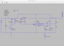
Can we go back to considering this for a moment? The 0.5A for the resistive load plus the current required to charge the capacitance at the input of the regulator under test (470nF in the case of the discrete design and 100nF in the case of the LM317 tests) flows from bench PSU->rail driver->DUT and back again. I think very little current flows from the signal generator as it is driving the bottom plate of the cap at the high impedance non-inverting input to the error amplifier. (See circuit of rail driver attached again - V1 is sig gen.) Very little current should be flowing through the LNA and sound card. Furthermore, if there were issues with the grounding connections/loop on this side of things I would expect tests that removed the reg DUT from the equation to have revealed them.
If you follow the board layout of the discrete regulator and consider the two wiring variants between DUT and rail driver, it is actually the second pic which has the shorter, more direct return path to the bench PSU. A connection from the reg DUT Faston tab to rail driver tab to which I have connected the bench PSU would provide an even shorter path. (The rail driver board has the same kind of GND plane typology with the sensitive regulator side of the GND plane semi-isolated from the input side via a spur connection.) The loop length on the V+ side is shorter with the soldered wire rather than the clip lead.
"voltage drop on input GND wire"
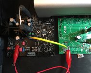
When I was monitoring the input stimulus ripple while testing, I merely clipped my scope probe to the Vout Faston connector at the output of the rail driver (where the red lead is connected in the 4th attachment) and clipped its GND lead alligator clip to the GND tab next to it. As measured there, the stimulus remained constant as frequency increased. Perhaps I should have checked what happened if I shifted the measurement points to the reg DUT.
I agree that a 74.8dB of attenuation is a long way from the 104-135dB signals I'm trying to measure from the output of the discrete voltage regulator. It is much more in line, however, with the signals measured when the LM317 board is the device under test (link).
You took a strict mathematical reading of my words - I used its broader sense in English as in "one thing combined with another" - the coupling relationship between the two undefined. But let's not debate my less mathematical use of English further.
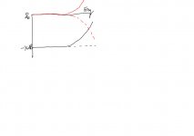
In the last graphic, I expected to see results resembling the curved black line in the plot, quite simply rising residual voltage with increasing frequency. Instead, I see something closer to the black dotted line. Is it not the case than the black dotted line can be obtained by passing the solid black line results through a low pass filter of the like depicted in dotted red? Alternatively, given the measurements represent the difference between two points the foregoing assumes a constant level for the reference with frequency. If instead the reference was rising in value with frequency at the same rate/amount, then the result measured would again look flat. Either produces flat results rather than increasingly higher voltages with increasing frequency. If the rising reference (or low pass filter) is a result of an unwanted problem with the test setup it masks a real outcome as flat instead of upward sloping.
I have trouble conceptualising how differences in GND potentials can develop if all the grounds are connected and I haven't really got my head properly around inductance (one and the same thing?). I know that a changing current across an inductor creates a voltage across it. In this testing, we have a DC current for the resistive load plus we need to charge and discharge the capacitor at the input to the regulator. Peak currents for the latter increase with frequency. So if, for example, the return path has inductance then as the frequency of interest increases the voltage developed across any GND inductance increases. Could this be the source of my solid red line? There was, however, less capacitance at the input of the LM317 (only 100n versus 470n) so peak currents there were less. (FYI the LM317 reg PCB doesn't have the spur configuration that I have on the others.) In any event, we come back to eliminating/reducing inductance and the points I made above about loop area.
I have to leave it at that for now. Time to put the kids to bed...
pafi said:Your expected result according to simulation is -170 dB @ 90 kHz. You achieved -124 dBV (after correction with stimulus amplitude it can be around -115 dB). The 20 dB/decade you were chasing is quantitative incorrect and due to the absolutely different levels totally irrelevant. Decreasing PSRR result is not improvement, but further error. Look at the numbers!
As Mark said once:
I don't imagine the external consultants who built those SPICE models for NXP, Motorola, Fairchild, Sanyo et al, were trying for 1 PPM (120dB) fitting accuracy. Nor do I imagine they achieved 1 PPM whether they were trying or not.
Yes, the sim of the discrete regulator produced incredible results. Were it the case that my test setup was unable to discern lower frequency outcomes from the noise floor I might have believed that the reason why we don't see a reduction in reg performance at higher frequencies is simply due to its performance being below measurement at all but the highest freq i.e. we only glimpse the far edge of the rising residual - it begins to rise much earlier but the performance is buried in the noise floor. But we are clearly able to see residuals above the noise floor at all frequencies.
So I care less about the absolute figures in the sim and instead note that a very core characteristic of such error feedback amplifier networks is reduced closed loop gain with increasing frequency available to 'combat' ripple. It's just not possible that PSRR doesn't decline with frequency. So, with respect to my discrete regulator, either PSRR performance begins to decline outside my test limits (above 90kHz) or, as I suspect more likely, the modelled performance is optimistic at all frequencies and it is better to expect a PSRR plot shifted the upwards.
At the same time, I also look to compare the results of my test set with a regulator that has been measured by others more skilled than I. Had my test setup measured the LM317 much closer to the performance plots by TI or data sheets I would have greater confidence that there isn't an issue with my test setup (whatever issue that may be) and been more comfortable with the results of the discrete regulator. But it didn't. I therefore critique my setup as best I can.
(BTW testing PSRR of this reg was meant to be a short 'side tour'. I had a PCB from an old regulator that could be easily modified to produce a rail driver. I was curious to see what the results would be. The short side tour is becoming much longer than expected. 🙂 )
I have a strong guess that the high current neccesary for rail driving flows through the GND wire and creating significant voltage on it. This voltage then creates a current in a loop probably formed by the GND of rail driver - rigol signal gen - mains - PC - soundcard GND - LNA output GND - LNA input GND - DUT. The loop current causes voltage drop on input GND wire and this is amplified exactly as any signal.
pafi said:Thicker wire doesn't make lower impedance at high freq. Smaller loop area does. So the thin twisted wires gives better connection.
Can we go back to considering this for a moment? The 0.5A for the resistive load plus the current required to charge the capacitance at the input of the regulator under test (470nF in the case of the discrete design and 100nF in the case of the LM317 tests) flows from bench PSU->rail driver->DUT and back again. I think very little current flows from the signal generator as it is driving the bottom plate of the cap at the high impedance non-inverting input to the error amplifier. (See circuit of rail driver attached again - V1 is sig gen.) Very little current should be flowing through the LNA and sound card. Furthermore, if there were issues with the grounding connections/loop on this side of things I would expect tests that removed the reg DUT from the equation to have revealed them.
If you follow the board layout of the discrete regulator and consider the two wiring variants between DUT and rail driver, it is actually the second pic which has the shorter, more direct return path to the bench PSU. A connection from the reg DUT Faston tab to rail driver tab to which I have connected the bench PSU would provide an even shorter path. (The rail driver board has the same kind of GND plane typology with the sensitive regulator side of the GND plane semi-isolated from the input side via a spur connection.) The loop length on the V+ side is shorter with the soldered wire rather than the clip lead.
"voltage drop on input GND wire"
When I was monitoring the input stimulus ripple while testing, I merely clipped my scope probe to the Vout Faston connector at the output of the rail driver (where the red lead is connected in the 4th attachment) and clipped its GND lead alligator clip to the GND tab next to it. As measured there, the stimulus remained constant as frequency increased. Perhaps I should have checked what happened if I shifted the measurement points to the reg DUT.
pafi said:You can add an ant to an ant, and get 6 dB gain, but if you add an ant to an elephant, then you see no change.
I agree that a 74.8dB of attenuation is a long way from the 104-135dB signals I'm trying to measure from the output of the discrete voltage regulator. It is much more in line, however, with the signals measured when the LM317 board is the device under test (link).
You seems to ignore the mathematical rules of logarithmic scales or rule of signal propagation. Addition happens on linear scale. Addition in linear scale is NOT attenuation.
You took a strict mathematical reading of my words - I used its broader sense in English as in "one thing combined with another" - the coupling relationship between the two undefined. But let's not debate my less mathematical use of English further.
In the last graphic, I expected to see results resembling the curved black line in the plot, quite simply rising residual voltage with increasing frequency. Instead, I see something closer to the black dotted line. Is it not the case than the black dotted line can be obtained by passing the solid black line results through a low pass filter of the like depicted in dotted red? Alternatively, given the measurements represent the difference between two points the foregoing assumes a constant level for the reference with frequency. If instead the reference was rising in value with frequency at the same rate/amount, then the result measured would again look flat. Either produces flat results rather than increasingly higher voltages with increasing frequency. If the rising reference (or low pass filter) is a result of an unwanted problem with the test setup it masks a real outcome as flat instead of upward sloping.
I have trouble conceptualising how differences in GND potentials can develop if all the grounds are connected and I haven't really got my head properly around inductance (one and the same thing?). I know that a changing current across an inductor creates a voltage across it. In this testing, we have a DC current for the resistive load plus we need to charge and discharge the capacitor at the input to the regulator. Peak currents for the latter increase with frequency. So if, for example, the return path has inductance then as the frequency of interest increases the voltage developed across any GND inductance increases. Could this be the source of my solid red line? There was, however, less capacitance at the input of the LM317 (only 100n versus 470n) so peak currents there were less. (FYI the LM317 reg PCB doesn't have the spur configuration that I have on the others.) In any event, we come back to eliminating/reducing inductance and the points I made above about loop area.
I have to leave it at that for now. Time to put the kids to bed...
Attachments

- Status
- Not open for further replies.
- Home
- Amplifiers
- Power Supplies
- Measuring PSRR