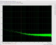
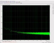
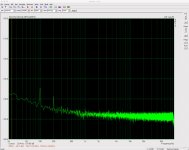
Screen shots. Got basically the same results today. According to my scope Vpp function the ripple stimulus was between 1.06Vpp and 1.02Vpp from 50Hz to 90kHz (slight decline as frequency rose).
Attachments


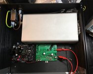
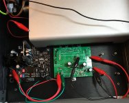
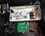
It's still bugging me that I had tested the LM317 with and without the preamp and gotten the same results. How then could it be a resistor in the preamp? My setup is identical to that before except this time I soldered the load resistor to the fasten GND tab rather than the GND pin at the output connector (V+ was soldered to the same spot as before). (And I used two clips leads to connect the rail driver rather than soldered wires.) Two pics of setup before and one of it now attached.
I might take another look at the LM317 before wrapping all this up.
I might take another look at the LM317 before wrapping all this up.
Attachments
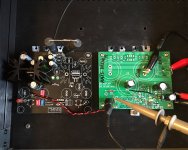
After the LM317 showed the same issues as previously and reconnecting the discrete voltage regulator only to find completely different results (and roll-off profile) I think I have realised at least one major problem with this test setup. The results depend on how (well) the rail driver and regulator DUT grounds are connected. I should have got this much earlier.
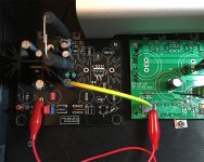
In the images above the grounds are connected through relatively weak, long connectors and in the case of the regulator DUT at a point with a thin spur to the main GND plane. (The idea of this spur in the ground was to encourage rectifier and filter caps pulses to circulate locally rather than impacting the ground reference for the more sensitive regulator components.) When I realised (to be honest by accident) that the results fluctuated depending on the impedance of the GND connection, I changed the setup to that pictured below.
Revised results:
Hz dBV/rtHz
50 -133.6
100 -134.3
200 -134.5
500 -135.0
1k -133.8
2k -131.3
5k -124.8
6k -123.0
7k -123.0
8k -122.0
9k -121.4
10k -122.2
20k -119.4
30k -117.6
40k -114.6
50k -112.1
60k -110.2
70k -107.6
80k -106.9
90k -104.5
(There's too much sound card frequency response drop off above 90kHz)
I think I've almost had enough of this for now 😛
Attachments

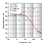
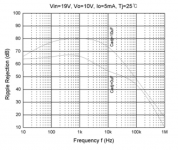
Even big companies get PSRR wrong -- I have pointed out the mistake to TI several times, but Fairchild has gets it right. One more thing-- it's helpful to use a lower load current, and a smaller perturbation signal when testing regulators for PSRR --
Attachments
Last edited:
Well I'm not sure I fully understand it. Presumably the ripple stimulus - good at the output of the rail driver on its own - is attenuated by the GND connection and something on the regulator DUT. Inductance in the ground connection and the 24R load? (It would be quite a lot of inductance to roll-off the stimulus 20dB by, say, 100kHz.)
I can imagine many situations where a voltage regulator of this type is connected to a rectified mains PSU with residual ripple by simple twisted pair wiring. Do such regulators benefit from their wiring (and mains PSU ground plane)?
I was checking the ripple stimulus at the output of the rail driver. I guess I should have measured it on the regulator DUT somewhere.
The load current is a function of making sure the regulator Cin is discharged appropriately. I presume the recommendation for lower perturbation signal is so that the load current can be lowered and hence these induction affects are lowered.
The load current is a function of making sure the regulator Cin is discharged appropriately. I presume the recommendation for lower perturbation signal is so that the load current can be lowered and hence these induction affects are lowered.
The output impedance of the regulator is inversely related to the load current.
Small perturbation signal -- we are looking for small signal effects.
Ugh it can't be attenuation of the ripple stimulus. Although I monitored this at the output of the rail driver these are connected circuits.
It must therefore be attenuation of the output of the regulator DUT. But quite how this is affected by the connection to the rail driver ground is escaping me.
It must therefore be attenuation of the output of the regulator DUT. But quite how this is affected by the connection to the rail driver ground is escaping me.
Jack, what load currents and perturbation signal levels would you suggest? I note from the articles you linked to AP seems to prefer levels as high as 0.5Vrms for the latter, more than 1Vpp, albeit their generator can't maintain that level for all frequencies of interest and so the Vin stimulus falls off rather rapidly.
An attempt at putting this measurement amplifier to work measuring PSRR of a PSU I have been working on. Comments welcome!
http://www.diyaudio.com/forums/powe...ild-sdip-bridge-rectifiers-8.html#post4853030
Hi,
What do you mean "this"? Who is Sam Groner, and where is any info about the amplifier? In the linked post I see only a photo.
I tried to follow your comments and understand what you done and what your problem is, but I realized I failed after 3 pages. There are results, but no clear description or detailed diagram about the test setup.
But quite how this is affected by the connection to the rail driver ground is escaping me.
Grounding is the most important part of every measurements. Improper grounding scheme can ruin completely a sensitive measurement. Im unable to see what you built, but I bet as soon as you draw a full schematic showing the impedances of the wires you will be able to analize or simulate the results you get.
Hi Pafi
Apologies. The reason is that the thread was split from another thread dedicated to Samuel Groner's Low Noise Measurement Amplifier, all the details of which you can read in his article for Linear Audio 3 (link), and had begun earlier in a thread dedicated to the development of the discrete voltage regulator itself.
The more general discussion in relation to measuring PSRR began in the latter (link). This included Mark referencing Walt Jung's original articles and sketching out an 'improved' rail driver. I provided a schematic of the rail driver in post 25 of this thread***. As the discrete voltage regulator I wished to test required a minimum 470nF of capacitance at its input, the rail driver and the load at the regulator DUT output had to be capable of charging and discharging this capacitance with sufficient slew rate. The maximum frequency of interest was set at 90kHz given the constraints of my sound card. With 12V output from the regulator DUT 24R for 0.5A was selected as a load. My initial results highlighted the issue I've been grappling with. As highlighted by Mark:
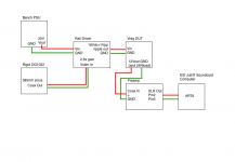
The test setup was straightforward. Bench PSU supplies 25V to rail driver. Signal generator supplies Vstim (385mV at the freq of interest) to the rail driver. The rail driver supplies 18V + 1Vpp ripple (gain of 2.6 x 385mV) to regulator DUT. Output of regulator DUT connected to the Groner LNA via coax. Output of LNA connected to the balanced input of my sound card. Post 45 provides a couple of pics (ignore the IEC inlet filter - I was repurposing another project's enclosure to provide some shielding).
I went through various tests of the sound card frequency response, the preamp and sound card combined frequency response, the rail driver etc etc. It did not occur to me that the ground connection between the rail driver and regulator DUT was so important since, as I mentioned above, I can imagine many situations where a discrete voltage regulator is provided DC with residual ripple from a separate mains rectifying PSU and that such connection is made simply with twisted wiring of the sort I used. Your input is much appreciated.
Regards
Steve
(*** In case it isn't obvious, in that LTspice schematic V1 is provided by my Rigol DG1022 signal generator at Vpp=385mV at the frequency of interest. V2 is provided by my bench PSU. The circuit was also convenient in that I had previously made a voltage regulator with much the same components and modifying a spare board to build the rail driver was therefore very easy.)
Apologies. The reason is that the thread was split from another thread dedicated to Samuel Groner's Low Noise Measurement Amplifier, all the details of which you can read in his article for Linear Audio 3 (link), and had begun earlier in a thread dedicated to the development of the discrete voltage regulator itself.
The more general discussion in relation to measuring PSRR began in the latter (link). This included Mark referencing Walt Jung's original articles and sketching out an 'improved' rail driver. I provided a schematic of the rail driver in post 25 of this thread***. As the discrete voltage regulator I wished to test required a minimum 470nF of capacitance at its input, the rail driver and the load at the regulator DUT output had to be capable of charging and discharging this capacitance with sufficient slew rate. The maximum frequency of interest was set at 90kHz given the constraints of my sound card. With 12V output from the regulator DUT 24R for 0.5A was selected as a load. My initial results highlighted the issue I've been grappling with. As highlighted by Mark:
Walton's measurements in #365 show a 20dB/decade degradation of line rejection at frequencies > 10K for all the best ones and many of the ordinary ones. Your data table in #362, does not. Why?
The test setup was straightforward. Bench PSU supplies 25V to rail driver. Signal generator supplies Vstim (385mV at the freq of interest) to the rail driver. The rail driver supplies 18V + 1Vpp ripple (gain of 2.6 x 385mV) to regulator DUT. Output of regulator DUT connected to the Groner LNA via coax. Output of LNA connected to the balanced input of my sound card. Post 45 provides a couple of pics (ignore the IEC inlet filter - I was repurposing another project's enclosure to provide some shielding).
I went through various tests of the sound card frequency response, the preamp and sound card combined frequency response, the rail driver etc etc. It did not occur to me that the ground connection between the rail driver and regulator DUT was so important since, as I mentioned above, I can imagine many situations where a discrete voltage regulator is provided DC with residual ripple from a separate mains rectifying PSU and that such connection is made simply with twisted wiring of the sort I used. Your input is much appreciated.
Regards
Steve
(*** In case it isn't obvious, in that LTspice schematic V1 is provided by my Rigol DG1022 signal generator at Vpp=385mV at the frequency of interest. V2 is provided by my bench PSU. The circuit was also convenient in that I had previously made a voltage regulator with much the same components and modifying a spare board to build the rail driver was therefore very easy.)
TI measurement guide you linked somewhere mentions a very important thing:
"However, the measurement is highly sensitive to setup noise, including noise from the probe-loop area and the layout of the printed circuit board (PCB)."
And this noise is not limited to random/uncorrelated noise. Every signal around the setup can and will radiate (electrical and) magnetic field that can induce voltage in the sensing loop, feedback loop, or GND loop(s) (I mentioned here the most probable/sensitive disturbance pick-up locations). Compared to the extremely low levels to be measured no iman not be considered insignificant. This is why GND connections strongly affects performance and/or measurement results.
However I couldn't identify which picture shows what test-setup, and couldn't follow and match the many different results (now I have 8 pages opened for your problem on mobile phone, and more would be neccessary, but I can't handle them), I have a strong guess that the high current neccesary for rail driving flows through the GND wire and creating significant voltage on it. This voltage then creates a current in a loop probably formed by the GND of rail driver - rigol signal gen - mains - PC - soundcard GND - LNA output GND - LNA input GND - DUT. The loop current causes voltage drop on input GND wire and this is amplified exactly as any signal. Unfortunately I cant find LNA input connection on the pictures.
This is not the only possible effect-chain...
Look at figure 5 in TI's guide! This is how a measurement setup should be shown. Every connection can be followed.
Look at figure 5 in TI's guide! This is how a measurement setup should be shown. Every connection can be followed.
I presume you mean one of the other figures, e.g. figure 6. Attached is a graphic matching the very straightforward description I gave earlier.
Bench PSU supplies 25V to rail driver. Signal generator supplies Vstim (385mV at the freq of interest) to the rail driver. The rail driver supplies 18V + 1Vpp ripple (gain of 2.6 x 385mV) to regulator DUT. Output of regulator DUT connected to the Groner LNA via coax. Output of LNA connected to the balanced input of my sound card.
I have also reproduced the photo from post 45 here for your convenience.
Below I list the initial results highlighting the lack of 20dB/decade roll-off in PSRR. The issue isn't "noise".
Hz dBV/rtHz
100 -136dB
500 -138
1k -139
2k -139
5k -136
10k -136
20k -134
30k -132.5
40k -130
50k -127
60k -127.5
70k -122
80k -122
90k -124.0
You can read the latest results above in post 64 but here are the main figures. I have also copied the image of the changed ground wire from post 64 as well.
Hz dBV/rtHz
50 -133.6
100 -134.3
200 -134.5
500 -135.0
1k -133.8
2k -131.3
5k -124.8
6k -123.0
7k -123.0
8k -122.0
9k -121.4
10k -122.2
20k -119.4
30k -117.6
40k -114.6
50k -112.1
60k -110.2
70k -107.6
80k -106.9
90k -104.5
Attachments

Last edited:
I ment figure 5 here:
http://www.ti.com/lit/an/slyt547/slyt547.pdf
Thanks for collecting data.
Your system drawing is now a good start. But some connections are missing: the mains inputs. Signal generator can be grounded, or at least has connection via Y capacitors. PC is most probably grounded. These or other elements not visible yet can give the reason of ground connection dependence. Inside the regulator PCB can also be connections responsible for the disturbance. In most cases there are multiple problems, not single.
Just because TI wrote "noise" (quite general term) it doesn't mean a periodic signal (stimulus) cannot coupled in here. It hapens all the time, even with professional equipments. Just read the effect chain I wrote.
Comparing the 2 setups above I see: a big inductive loop (antenne) in interconnection between DUT and rail driver creates unwanted transmittion increasing with freq. while the twisted wire pair's lower self-inductance and self-cancelling magnetic field creates less (and not so much freq dependent) or no disturbance. Quite expected behaviour. Shielded cable would be even better. But I can't see the internal structure of your regulator PCB, and the coupling effects here can exceed (therefore hide) or modify the effect of the interconnect cable.
Thanks for the link. It had not been referenced before and so I had no idea that was the document you were referring to.
The bench PSU, signal generator and PC are all grounded and into the same mains socket.
The twisted pair setup failed to produce the expected results. The pic on the right with the heavier ground connection was more in line with expected - a 20dB/per decade rolloff in PSRR with increasing frequency beyond circa 10kHz.
Once again, the issue was a masking of reduced PSRR - the measured output ripple residual had less than expected slope beyond 10kHz.
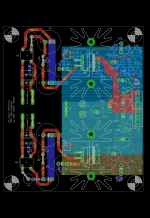
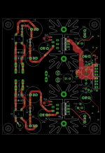
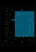
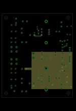
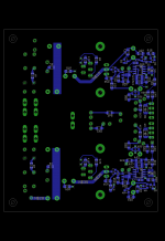
(FYI Some images of the discrete voltage regulator board layout attached. All layers; top layer; second layer which is basically ground plane; third layer which is V- plane; and bottom layer. You can see from the photos above that the minimum input capacitance of 470nF was placed at C7, in lieu of the circuit's main CRC filter network, and the 18Vdc+1Vpp ripple stimulus output of the rail driver connected just before it. The annotated circuit attached should be enough.)
The bench PSU, signal generator and PC are all grounded and into the same mains socket.
while the twisted wire pair's lower self-inductance and self-cancelling magnetic field creates less (and not so much freq dependent) or no disturbance. Quite expected behaviour.
The twisted pair setup failed to produce the expected results. The pic on the right with the heavier ground connection was more in line with expected - a 20dB/per decade rolloff in PSRR with increasing frequency beyond circa 10kHz.
Once again, the issue was a masking of reduced PSRR - the measured output ripple residual had less than expected slope beyond 10kHz.
(FYI Some images of the discrete voltage regulator board layout attached. All layers; top layer; second layer which is basically ground plane; third layer which is V- plane; and bottom layer. You can see from the photos above that the minimum input capacitance of 470nF was placed at C7, in lieu of the circuit's main CRC filter network, and the 18Vdc+1Vpp ripple stimulus output of the rail driver connected just before it. The annotated circuit attached should be enough.)
Attachments

Last edited:
I found the link following your links, maybe not you but somebody else linked it. Toooooo much branches.
Why do you expect worse result? Because somebody got something like it, or do you have simulation result like it? The first reason is incorrect. Other people also can make mistake. Maybe you did it right in first setup. Im quite sure the better result is more correct.
Thicker wire doesn't make lower impedance at high freq. Smaller loop area does. So the thin twisted wires gives better connection.
Grounding everything is a known reason to get false results. Most pro methods use special isolation transformer to couple stimulus without ground loop (however above 100...1000 kHz they usually create other problems...).
The same socket only helps to reduce 50/60 Hz problems. The effect chain I described is still there.
I will check the layout, but currently I find you are unsatisfied because you made a good measurement first instead of a bad one like somebody other. ;-)
The pic on the right with the heavier ground connection was more in line with expected - a 20dB/per decade rolloff in PSRR with increasing frequency beyond circa 10kHz.
Why do you expect worse result? Because somebody got something like it, or do you have simulation result like it? The first reason is incorrect. Other people also can make mistake. Maybe you did it right in first setup. Im quite sure the better result is more correct.
The pic on the right with the heavier ground connection
Thicker wire doesn't make lower impedance at high freq. Smaller loop area does. So the thin twisted wires gives better connection.
The bench PSU, signal generator and PC are all grounded and into the same mains socket.
Grounding everything is a known reason to get false results. Most pro methods use special isolation transformer to couple stimulus without ground loop (however above 100...1000 kHz they usually create other problems...).
The same socket only helps to reduce 50/60 Hz problems. The effect chain I described is still there.
I will check the layout, but currently I find you are unsatisfied because you made a good measurement first instead of a bad one like somebody other. ;-)
Hi Pafi
I don't think you have thought enough about issue at hand. The initial results look great - but simply aren't credible. From post 72 addressed to you:
I've attached a graphic of Jack's results hereto.
I also invite you to reflect on post 10 above and this post which has the results of when I tested an LM317. In the latter, the attenuation is extremely apparent.
The issue is not the coupling in of external periodic signals. The issue is attenuation of the measured output. I suspect an inductor (low pass) filter created by the ground setup but the inductance has to be quite large, however, to create with the 24R load a low pass filter down 20dB at 100kHz. Still thinking about it.
I don't think you have thought enough about issue at hand. The initial results look great - but simply aren't credible. From post 72 addressed to you:
Originally Posted by Mark Johnson
Walton's measurements in #365 show a 20dB/decade degradation of line rejection at frequencies > 10K for all the best ones and many of the ordinary ones. Your data table in #362, does not. Why?
I've attached a graphic of Jack's results hereto.
I also invite you to reflect on post 10 above and this post which has the results of when I tested an LM317. In the latter, the attenuation is extremely apparent.
The issue is not the coupling in of external periodic signals. The issue is attenuation of the measured output. I suspect an inductor (low pass) filter created by the ground setup but the inductance has to be quite large, however, to create with the 24R load a low pass filter down 20dB at 100kHz. Still thinking about it.
Attachments
Steve -- did you run a calibration curve (Frequency Response Calibration) in ARTA prior to running the test. The Zin of the regulator will have its own impedance curve.
Hi Jack. See post 4 of this thread for one test of this. I did not do a loopback with the sound card as the stimulus, but rather did it the slow and cumbersome way. I think it still proved the pre-amp and sound card combo to be flat (enough for these purposes anyway). The sharp roll-off in the FR of the sound card capped my measurements at 90kHz (see attached).
PS: Apologies to Pafi as it was in fact me that posting the link to the TI article. I had not read his post properly and had thought he was referring to the AP guides posted by Jack
PS: Apologies to Pafi as it was in fact me that posting the link to the TI article. I had not read his post properly and had thought he was referring to the AP guides posted by Jack
Attachments

- Status
- Not open for further replies.
- Home
- Amplifiers
- Power Supplies
- Measuring PSRR